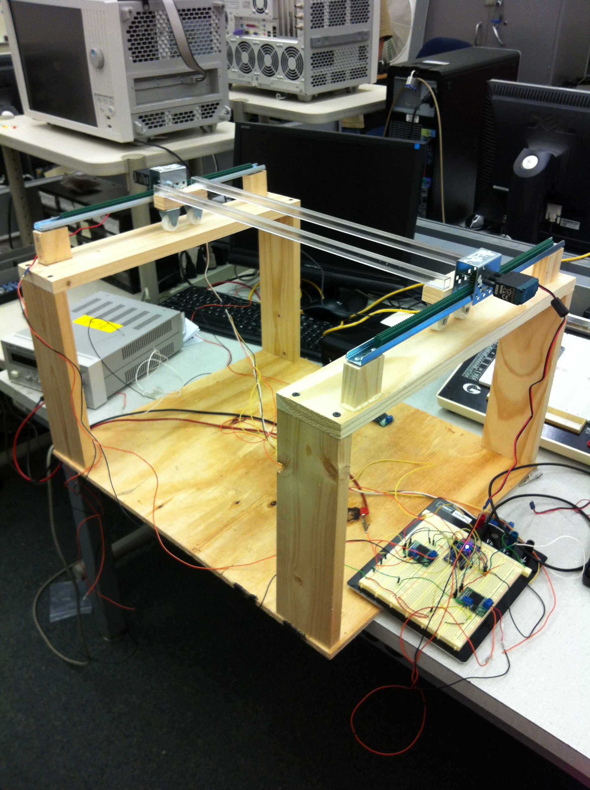
Since the last time, the rig’s got one new edition: racks to enable movement in one direction. It looks like this:
And video of “movement”:
I should have known better than to film vertically… The program runs a simple movement command for a short time, at the end of which I reset the microcontroller and step back to get the shot. Let it be known I do terrible prototype wiring. It will no doubt be cleaned up as we progress.
That being said, it’s awesome to finally see movement, after having so many setbacks. There was going to be another problem though: the motor movements are tracked with an encoder on one of the motors, just one though, so it’s possible the other one will lag. That’s been fixed by changing the other motor to one with an encoder, so this picture actually isn’t the one that’s most recent.
I thought programming was going to be a huge headache. And it was/is. I don’t know a whole lot about controls, and until I know a little bit more, movement is going to be a little naive: move towards desired position at full speed, and ramp down speed as platform approaches.
Here was another thing that was testing me as I was programming. The vex motor encoder is an i2c device, and the mbed microcontroller only has two i2c sda/scl pair of output pins. We are using a minimum of at least 3 encoders, so at least two encoders will be put on the same bus. To distinguish between the encoders on the same bus, you have to change their address (I’ll assume you know the basics of i2c from here). According to the datasheet for the encoder, you can change the address by opening up communication with the default address of 0x60, then writing the value 0x40, which is the address of “change default address” register, followed up by a final write of the desired register address (which should be in the range of 0x20-0x5E). The mbed i2c library is a little strange, because these two should do the same thing…but they don’t:
char changeAddr = 0x4D; // change address register
char newAddr = 0x20; // new address
i2c.write(0x40, &changeAddr, 1); // tell encoder I want to change default address
i2c.write(newAddr); // write new address

// that didn't work, but this did:

char changeAddr[2] = {0x4D, 0x20}; // put values to write in an array
i2c.write(0x40, changeAddr, 2);
the mbed’s i2c API specifies two versions of the write method, write(addr, char*, int) where the first argument is the address of the device, the second is a pointer to the values being written (hence why in the first try, and the third is the number of bytes to write. The other write is just write(byte) which writes a single value on the line. I thought after sending the device the value 0x4D, it knows that I am sending a value of the new address I want. But that can’t be done in a separate write. The “write” method includes the start and stop commands, so that was probably why. That took me way too long to figure out. Not enough experience working with i2c I suppose.
The encoders are also a bit different from other i2c devices in that multiple devices on a bus are actually daisy chained together, as opposed to devices attaching themselves to the bus like the other devices I’ve worked with, and there is a register that tells each device in the chain whether to pass through the clock and data along. If it does not, it is called a terminator. This is set in a register. If you do in fact want an i2c bus, you must disable the terminator register, and the next device can be initialized just as in the above.
Hopefully this phase of the programming will be done soon, and what I learn can be applied to movements in the other axis.
