Stepper Motor Music [on hold]

Time to report in with a fun little project (sort of). I saw this some time ago:

It’s very cool, and I enjoyed it immensely so because I am not very musically inclined, however much I’d like to be. There is almost a…genre of this kind of music, and it’s a lot of fun to listen and watch:

It should be noted the creator of the first video also wrote the score. This seems a great hassle to me, so I wanted this to be able to be supplied an already created score. There isn’t a whole lot of detail about the project, so I set out to recreate the project, which I thought would be a fun project to occupy me for a few days this summer, a week tops. For the record I started this about a month ago, and it still remains unfinished :[ due to a combination of some missing resources, and time (seriously, I was looking forward to playing so many videogame melodies). It’s sadly gathering dust right now and I’ve to pack it away for the moment, but before I do, I’m going to write down all my thoughts about it, so that I, and even anybody else, can hopefully finish it.

2014-07-25 22.23.26
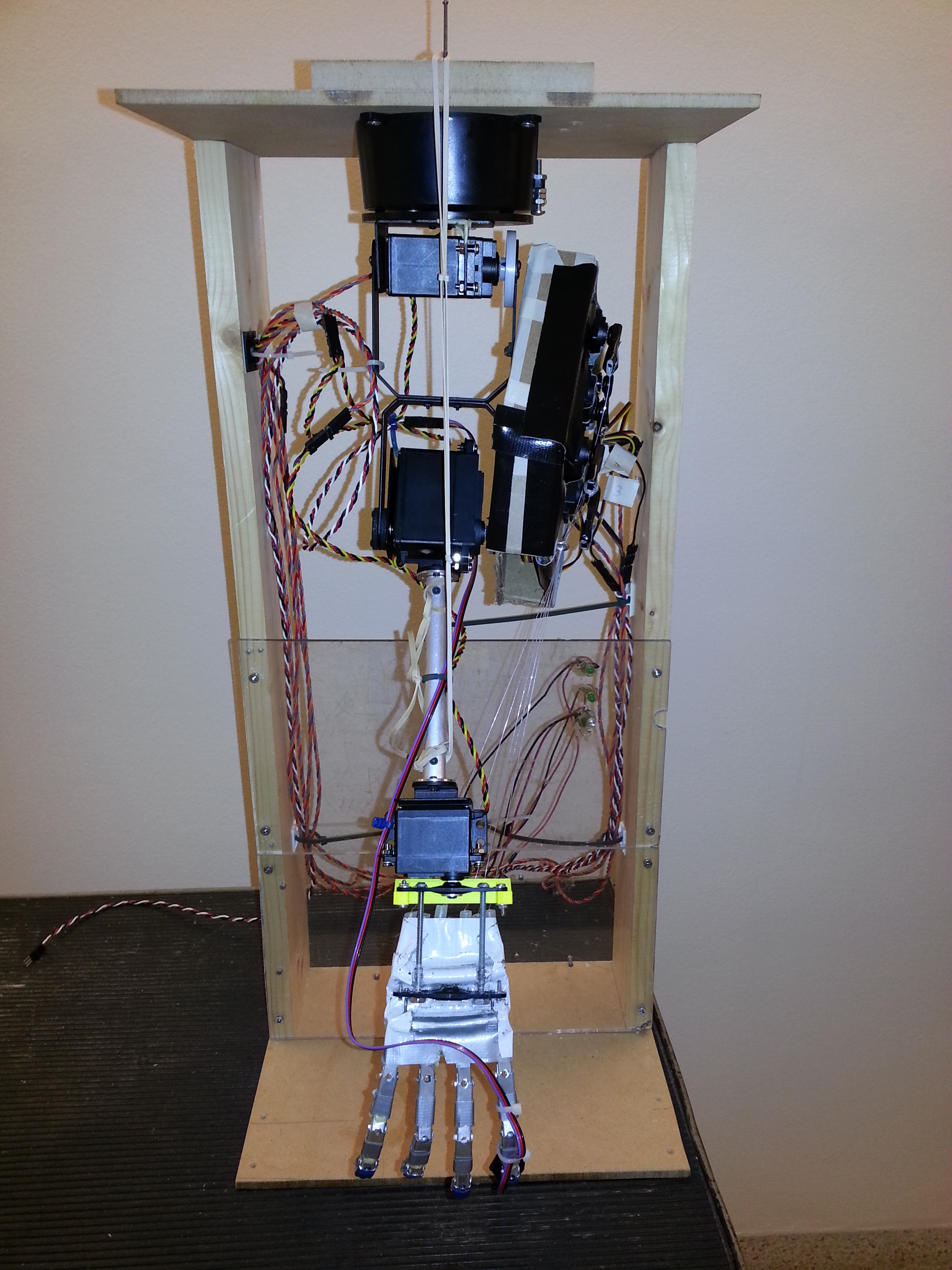
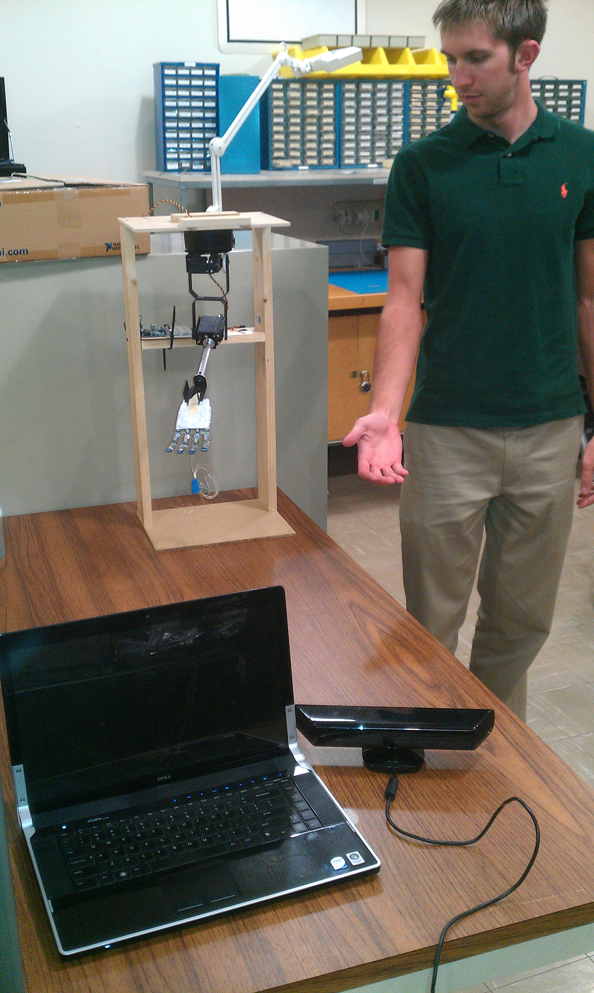
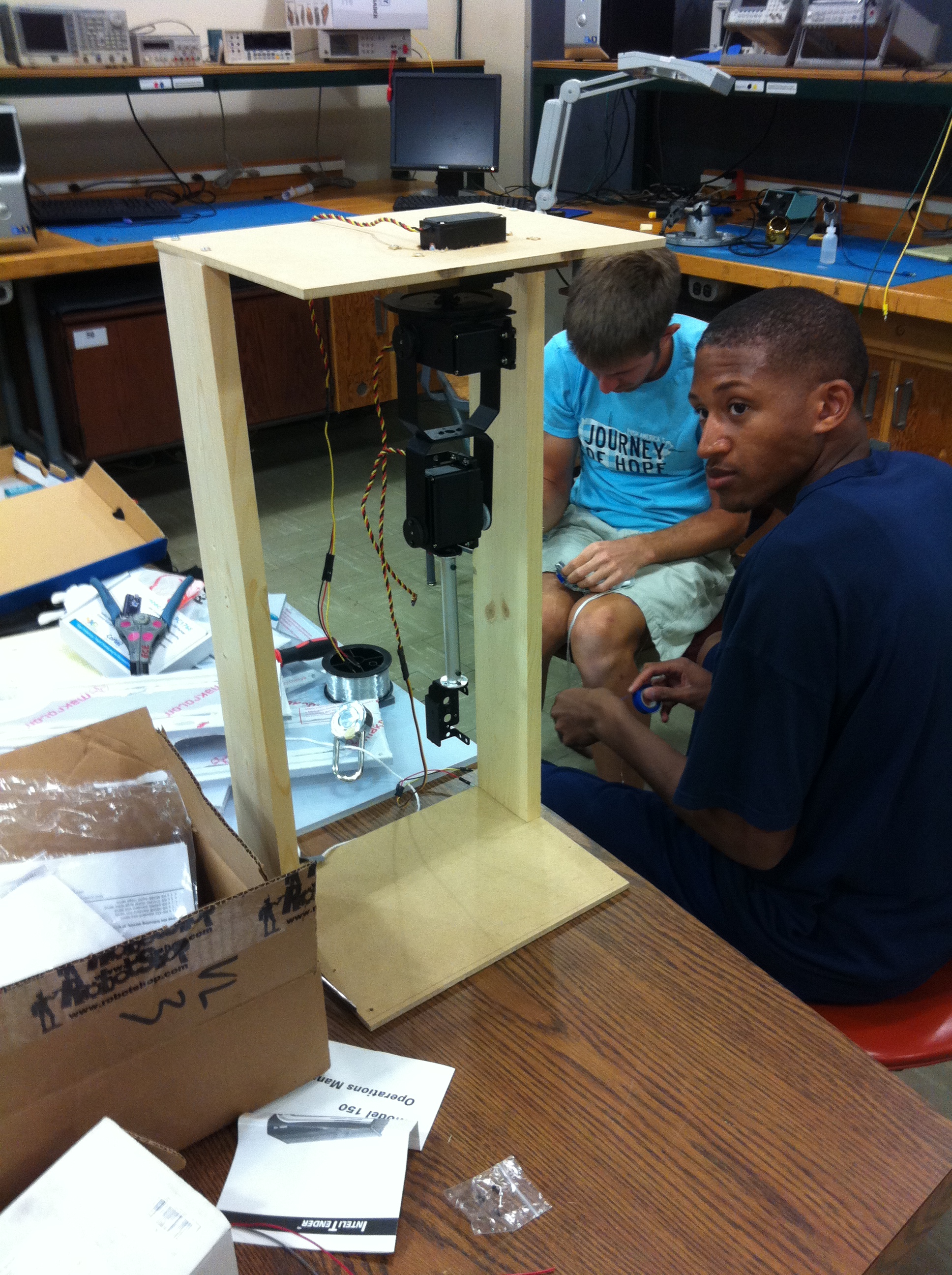
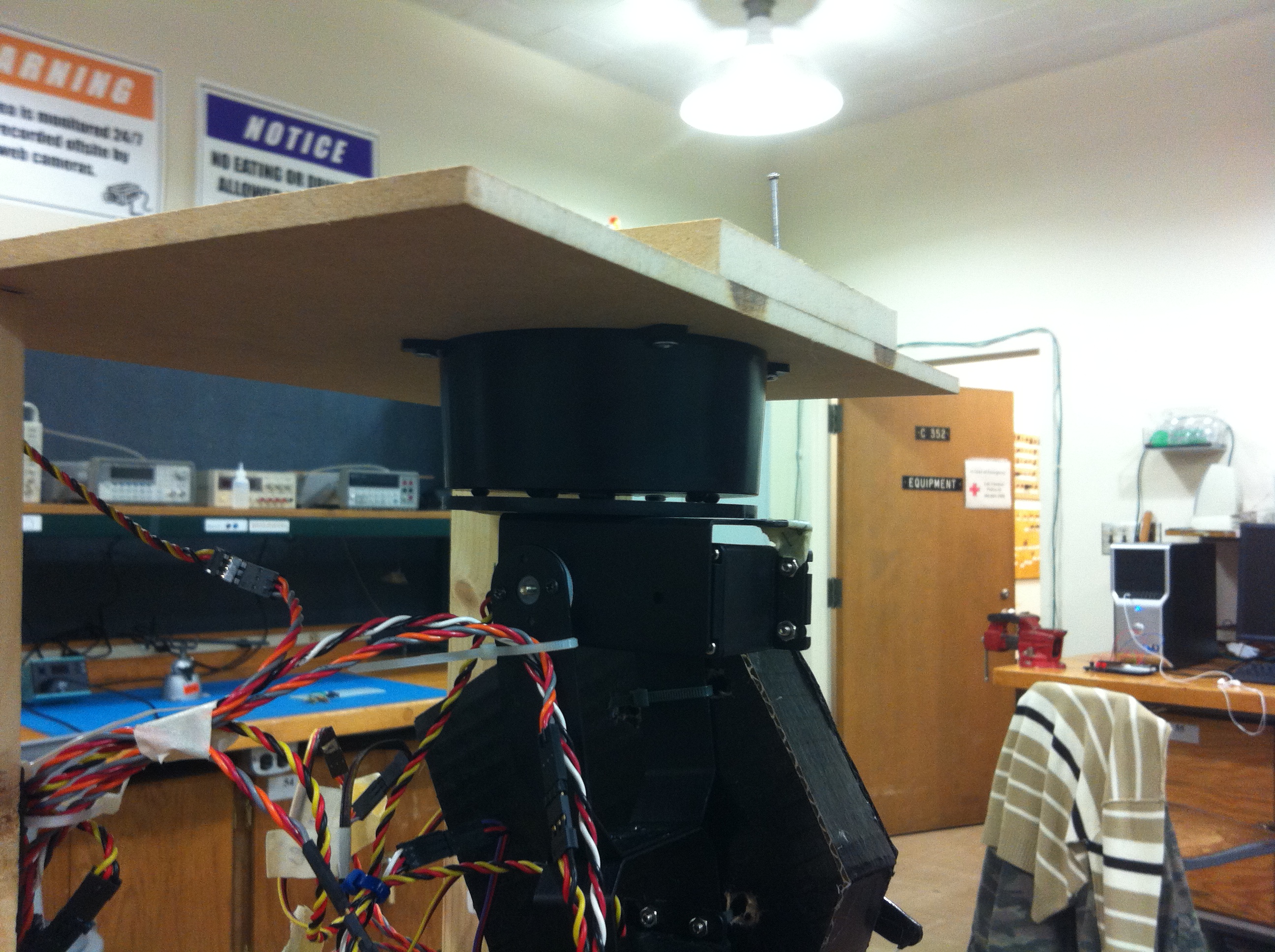
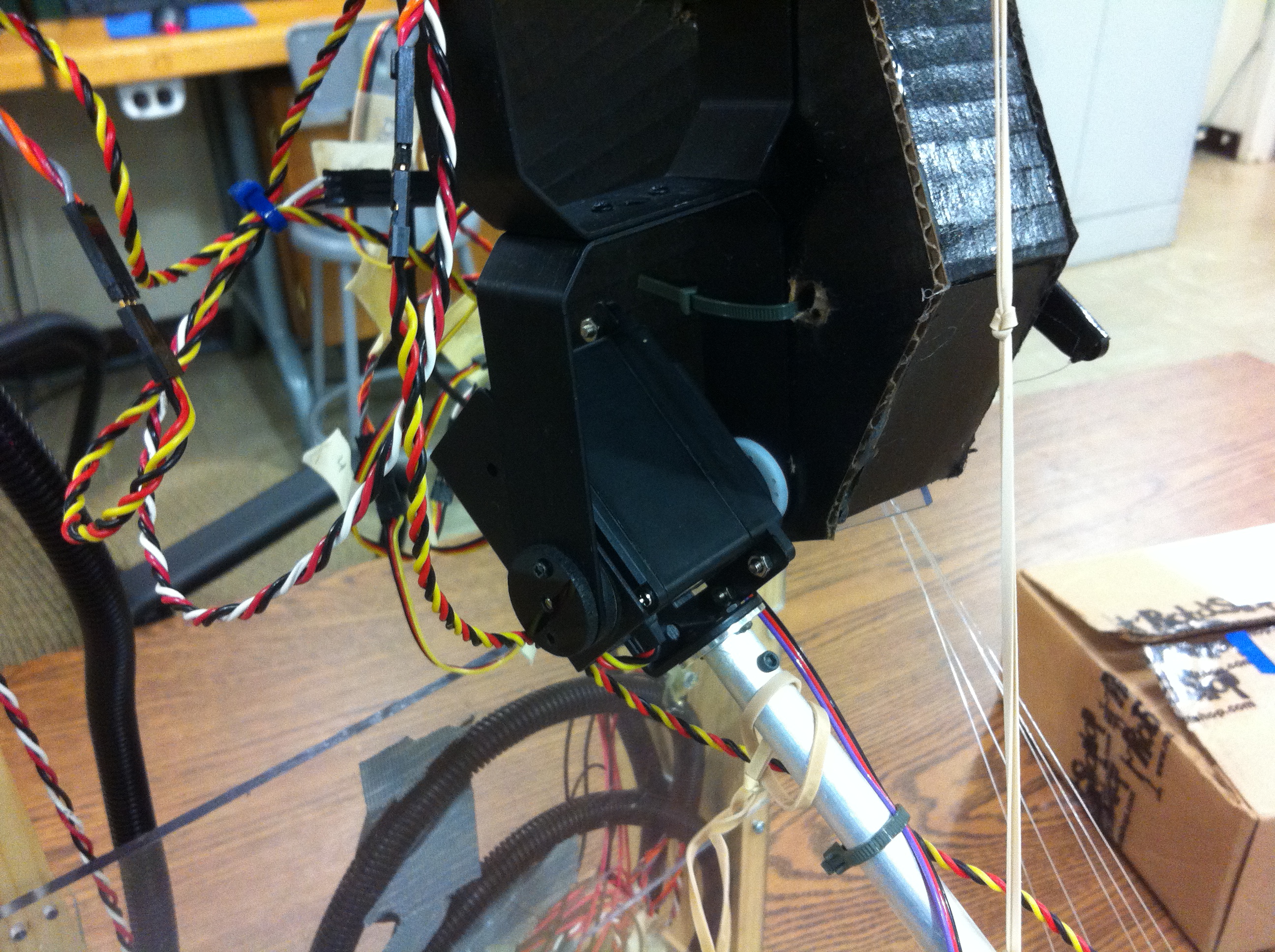
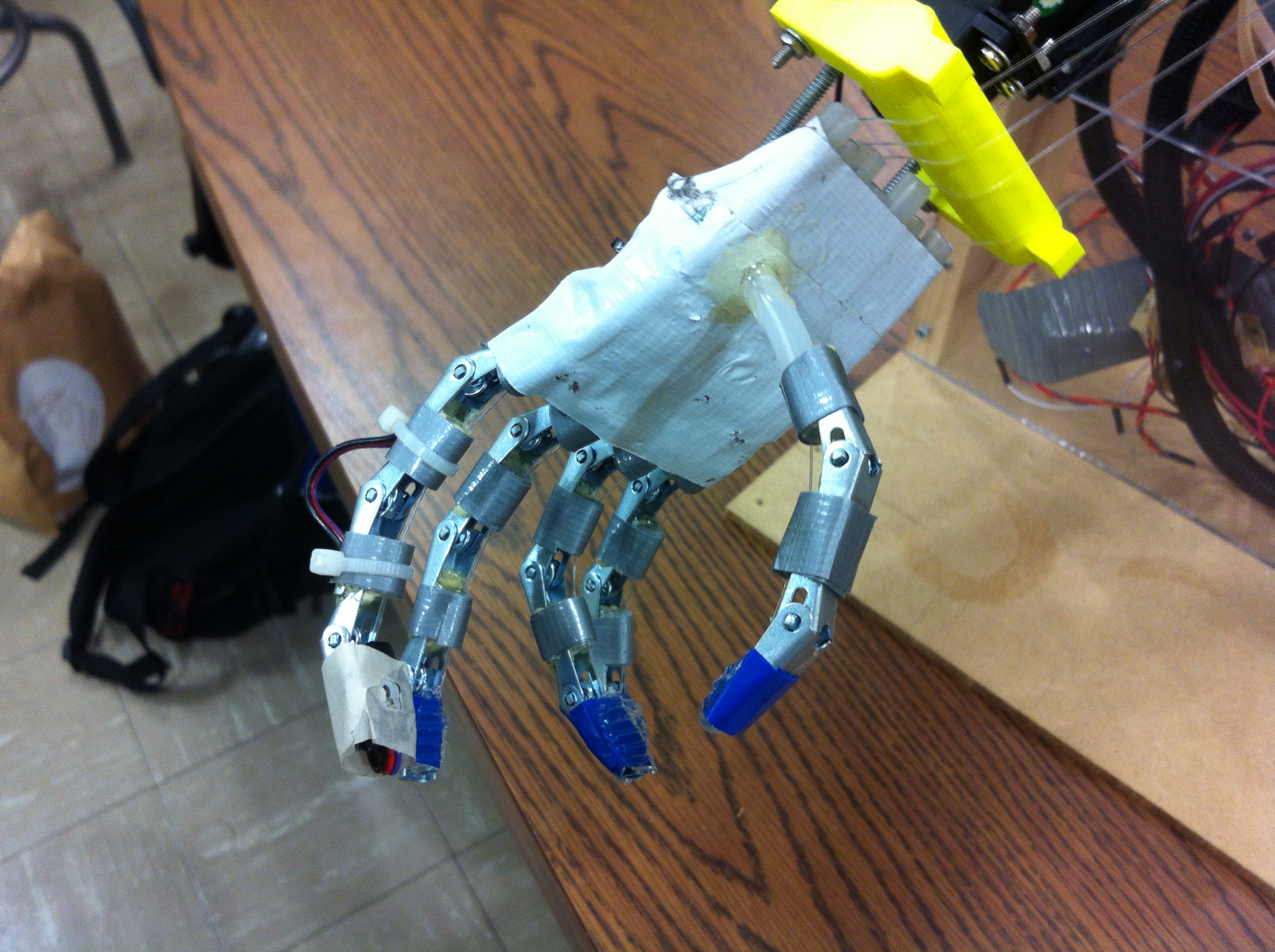
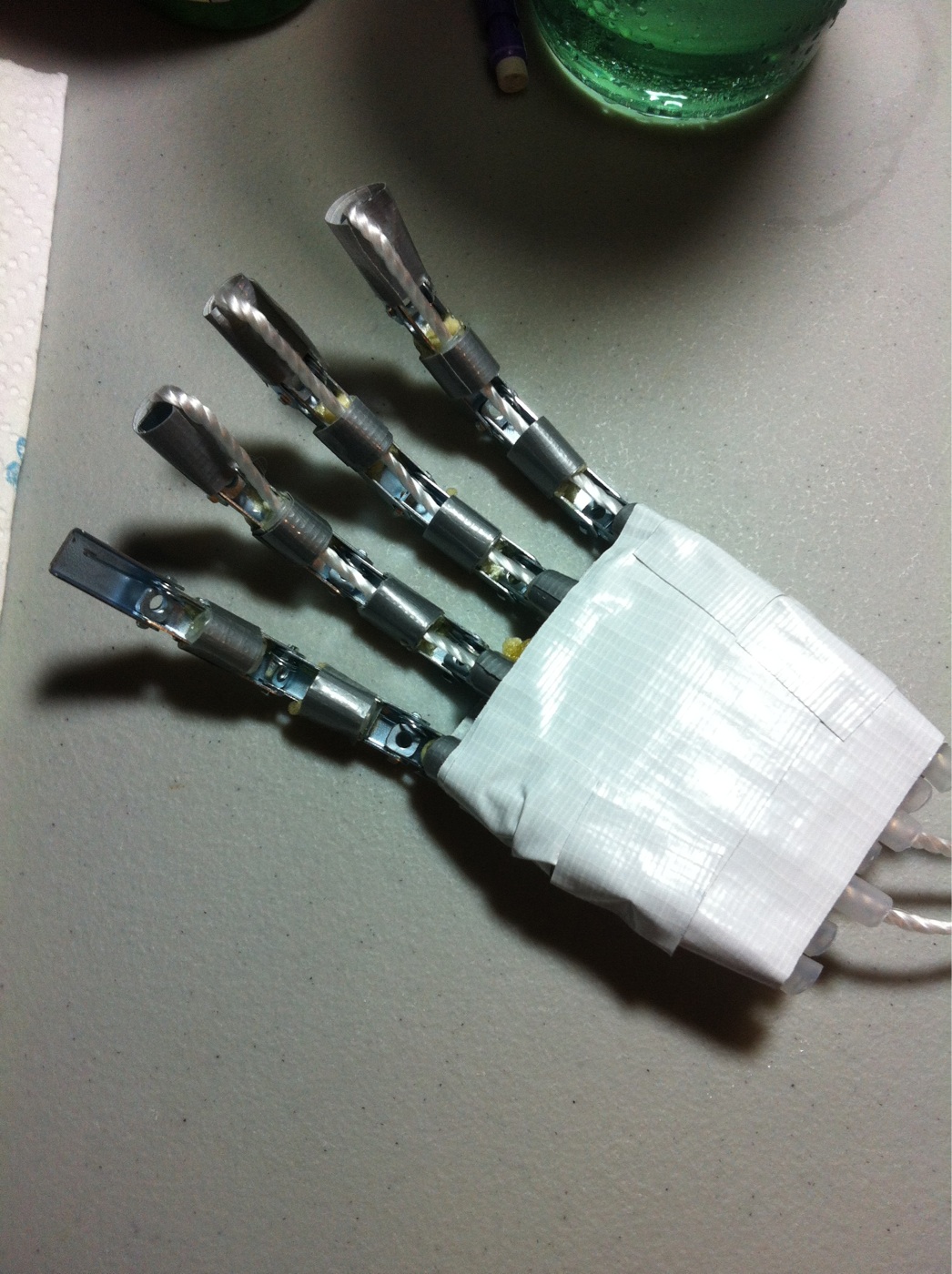
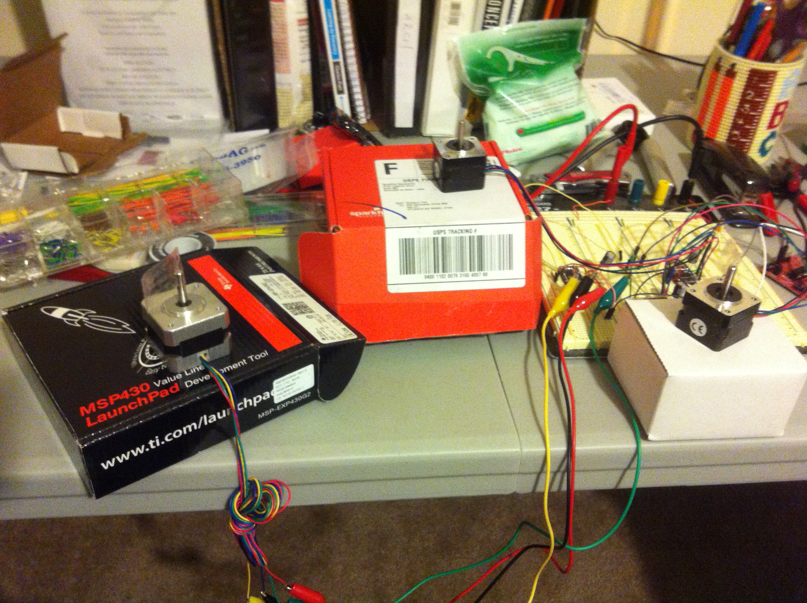
(the current state of the project)

So let’s get into it:

What you’ll need:

– Stepper motors, this is your “instrument”. The ones pictured above are SM42BYG011 and two SY35ST28. Simply because I had them on hand.

– Drivers. The ones used above are all DRV8825’s (http://www.pololu.com/product/2133). The datasheet also suggests putting some decoupling capacitors across the power source (at least 47uF)

– An MCU of your choice. The creator of the video from which I am drawing inspiration from is using an Arduino, but I decided to use an MSP430 launchpad, simply to double this as an exercise for learning how to program MSP430s, and that I had one lying around.

How it works:

– MIDI: (ripped straight from wikipedia) short for Musical Instrument Digital Interface, is a technical standard that describes a protocol, digital interfaceand connectors and allows a wide variety of electronic musical instruments, computers and other related devices to connect and communicate with one another.[1]

A MIDI device is essentially what we’re creating. We’re going to start with a .mid file containing music that we’d like to play, and decode it’s information to get which note to play, for how long, and which channel (instrument, steppers in this case). Another reason this project looked so attractive is because I knew this to be done already, thanks to miditones created by Len Shustek: https://code.google.com/p/miditones/. His code takes a .mid file, and generates an array of integers that will specify the start of a particular note on any one of up to 8 channels, the end of that note, and any delays that needs to be implemented inbetween. The specifiers are explained in the source code. Here’s what I get when I run it on Daft Punk’s Get Lucky (gotten from here http://www.free-midi.org/song/daft_punk-get_lucky_ft_pharrell_williams.html):

char score[] = {
0,50, 0x90,31, 1,194, 0x80, 0x90,31, 1,244, 0x80, 0x90,31, 1,244, 0x80, 0x90,31, 1,244,
0x80, 0x90,50, 0x91,66, 0x92,62, 0x93,59, 0x94,35, 0x95,35, 0,26, 0x80, 0,98, 0x90,50, 0,26, ...

So this says to 1) delay for 50ms 2) start playing note 31* on channel 0 3) delay for 194ms 4) stop playing on channel 0…and so on. As the most musically challenged person the planet, it couldn’t be clearer if it was spelled out for me.

*Various charts of how midi notes are commonly corresponded to musical frequencies are available, ex: http://www.phys.unsw.edu.au/jw/notes.html

– The steppers: if you have no knowledge of stepper motor operation…well it actually won’t hurt you very much if you do buy the driver listed above, or a similar one (but you should still take a moment to read up on it, it’s fascinating). What you need to know is that stepper motors move in series of “steps”. This mechanical motion is audible, so you can “play music” by making the motor move a certain number of steps per second. For example, if I excite the motor 261-262 times per second, I am approximately playing middle C. The driver make this simple because there is only one connection between the stepper and driver that you need to worry about, and that is the “step” input. This input on the driver accepts a series of pulses, and will increment the stepper one step per pulse.

General program flow:

Well, obviously this part isn’t working, or I’d be posting about a completed project right now…I thought it would be straightforward (and maybe it actually is, but I’ll discuss the problem in a moment).

– A main loop keeps a pointer to the current “action” specified by the output array of miditones, and controls several flags that sets whether the system is currently playing music and/or delaying, and changes the notes directed to each channel.

– An ISR (or several) is used for timing so that delays can be implemented properly, as well as sending pulses to the steppers.

Issues:

So why aren’t I done?

Actually, I might be. So one obstacle I’m running into is that I don’t have enough physical channels to play all the music I want to. miditones analyzes the .mid files and outputs information on up to 8 channels, but I only have 3 steppers. Have I tried playing with only 3 channels? Yes, and it definitely sounds incomplete, and very disappointing. If I could just borrow some steppers, maybe this project can come out of project purgatory.

With that said, if anybody should like to try to complete this project, leave a comment or send me an email and I’ll send the source code.

Pick a number between 0-9

While cleaning up the semester’s mess, I came across this pamphlet:

2013-12-18 17.04.05

I have no idea where it came from, but I looked through it, and found some interesting circuits, such as this one:

2013-12-18 17.04.27

It’s a “random number generator”. There are two main components: an oscillator circuit and a decade counter, pretty much split down the middle. About each one…

Oscillator

This involves the two NAND gates on the left. If you’d like, you can replace then with inverters, however, because tying the inputs of a NAND gate together produces the same function as a NOT (check: 1 NAND 1 = 0, 0 NAND 0 = 1).

Putting inverters together in a circuit with feedback creates an oscillator, like so:

nand_oscillator

And depending on the value of the resistor and capacitor, you can make it oscillate at different rates.

Decade counter

“Decade” means 10, so a decade counter counts to 10. The specific IC used here (4017) has 10 output pins that are driven high depending on the current count, instead of 4 pins that represent 0-9 in binary. Counts are advanced by a clock, so the oscillator output circuit connects to the decade counter at the clock pin, and the circuits are separated by a pushbutton.

To see what pin is being driven high, and hence see the current count, you can put a LED in series with each output pin, and the LED will light according to the count.

When the pushbutton is activated, the decade counter sees the oscillator output and will begin counting. If the oscillator is operating fast enough, seemingly “random” numbers can be produced by letting go of the pushbutton.

Because I’m on break and I just happen to have the components and ICs on hand, I built it.

Senior Design: Robotic Arm with Kinect Interface – Detailed Report (long post)

In this post I will detail what my group (Cameron Reid, Carlton Beatty, Chris Stubel, and myself, Ben Yeh) have been on since September. Allow me to present, my senior design:

Robotic Arm with Kinect Interface

*https://github.com/pyeh9/Kinect-Controlled-Arm (Github repo of code)

To put it simply, it’s a robot arm that copies you. Think motion capture, but the results you see in real time on hardware.

arm best picture user arm 1

Isn’t she a ‘beaut? Now if I had just said “robotic arm”, I’d think the the typical reaction would be, “ppfftt, what’s so special about that?” Two things makes this stand out.

hand6

The first is the end affector. We did away with the standard open and close claw, and attempted to fashion something that looks and moves like the human hand. Admittedly, functionality wise, it’s not so different from the claw in that the hand simply opens and closes, but it’s a step towards a dextrous hand in the future.

User with armglove3

Second is how it’s controlled: via the Kinect and a custom sensor-glove. With this, the arm copies YOU in (almost) real time. Let me show you this thing in action:

and another:

As advertised, observe the arm is roughly going through the exact same motion as me.

Application

I did not build this thing in mind with any one specific application. What I wanted was an intuitive interface for controlling a robot. This robot could then be sent out into situations that humans can’t or shouldn’t go. Imagine, if I could put some wheels on this bad boy to make it mobile, and I had another one for the other arm, this thing might be able to administer disaster relief, bomb disposal, become a field medic, collecting samples in deep sea diving, firefighting, etc..

It’s also my first foray into the field of robotics, however cursory it was. I did not focus my coursework on robotics or controls at all. In addition, just about everything was built (read: hacked) from scratch.

If nothing else, I had a lot of fun building this thing, and I think it’s really freaking cool. Here’s a video of the group messing around:

HOW IT WORKS

At the highest level the system consists of: a Kinect, a PC, a microcontroller, and the rig (arm). Here’s a component diagram:

block diagramA user stands in front of the Kinect which does some black magic to track the user’s arm’s position (just the arm though, up to the wrist). This is in conjunction with the glove with tracks the user’s hands. The glove hardware is simple enough to be processed by one uC (an Arduino UNO in this case), but the Kinect’s sensor information is processed by a program (written in visual C++), then sent to another microcontroller (also an Arduino). The Arduinos then actuate the motors according the to data that was received.

Let’s go into more detail about how it works. This will be broken down into hardware (construction of the hand, arm, and glove) and software (using the Kinect, uC programming), and some misc.

Building the arm

Having very little resources, and no knowledge about commercial robot platforms (which would most likely be out of budget anyway), we set out to create out our project out of something very minimalistic. What we found was the AL5D by Lynxmotion (http://www.lynxmotion.com/c-130-al5d.aspx).

AL5D arm upright chassis with arm

That doesn’t look very human-like, so we constructed a chassis and slapped it upside down to the top, which looked like the right picture in the beginning stages. Let’s zoom in each joint.

shoulder close up 1

This is the shoulder. There two two degrees of freedoms afforded here. The first I will call the “base”, and it swivels about the vertical axis, controlled by one servo motor (hidden inside the case that’s connected to the top). The second I will call the “shoulder” (terrible naming, these two movable parts I also collectively call the shoulder), which rotates about an axis perpendicular to the vertical axis, and also controlled by another servo.

elbow close up 1

This is the elbow. It bends just like the human elbow does, and is controlled by another servo.

wrist close up 1

This is the wrist. It rotates about the axis made by your forearm (it moves like the Queen’s wave). And you guess it, it’s controlled by another servo. You might wonder if it can bend, and the answer’s unfortunately no. Tracking the wrist and hand proved to be difficult, so we did away with this movement possibility.

All together, the arm (minus the hand) provides 4DOF, so it’s not quite able to mimic a human arm fully.

Building the hand

The hardware for the arm was about $150, but this nifty “hand” will run you just around $25 and your afternoon. This is actually a pretty popular design for the hobbyist’s animatronic hands. What you need is something with some natural tension/springiness. We found these things called toggle bolts. They’re made to affix things into walls. The flap is spring loaded, so that it can be closed and fed through holes and expand on the other side. We’re just interested in the flap part. If you overlay a few of these together, and introduce some tubing, you can make yourself a “finger”

finger2(for the record, RIPD was not a very good movie)

By tying a string to one end, and pulling on the other, it will bend in a way very similar to a real finger. Put a couple of these fingers together and you’ll almost have yourself a hand. Observe:

The thumb placement was tricky. We eventually settled on placing it directly opposite the rest of the fingers, even though a real thumb is not this restrictive. It still ended up working well enough.

hand1Building the glove

For reasons that will be explained later, we built a glove to control the hand portion of our arm.

glove

Just like the hand, this is also a fairly common maker’s project. The yellow stripes on the fingers are flex sensors, which are essentially potentiometers that react to bending. One way to use this is to make a voltage divider with these and feed the output to an ADC so as to monitor how you are bending your fingers. The red breakout board is an accelerometer. This is used to detect the tilt of the wrist. Depending on the orientation of your wrist, the force of gravity breaks down into vary components along the standard coordinate axis, like so

wrist_explanation

For now, this is all wired to the Arduino through a cable that connects to the perfboard circuit on the back of the hand.

Utilizing the Kinect

Even more so than the entire team’s lack of mechanical engineering and robotic knowledge, the whole project would have been a lot harder without the Kinect. I had played with the Kinect before so I knew that it was capable of skeletal tracking. By skeletal tracking, it means we are able to leverage the Kinect’s various sensors, and through programming with the SDK provided by Microsoft, to produce such a representation of the human body:

angle explanations

In addition to planar coordinates, the Kinect features a few depth sensors, so that it is actually able to provide coordinates of each joint IN SPACE. Moreover, all this requires is a few lines of code in the SDK. Then what we do is we extend vectors between say, the elbow and shoulder (call this A), the elbow and wrist (call this B), and use the relationship A dot B = |A||B|cos(theta) to get the angle between them. To get other angles, it remains to find the appropriate reference angles.

When it gets an angle, it then sends it over serial to an Arduino.

Arduino programming

Let’s consider Arduino one in the block diagram in the beginning. All this is responsible for is reading the various sensors on the glove and actuating the motors for the hand accordingly. For example, when I fully flex my index finger, there is a software mapping of this reading into the angle that the motor connected to the index finger is supposed to turn to. The accelerometer is an I2C device, and we similarly extract the acceleration magnitude in each coordinate axis, and use some trig to get the wrist tilt angle.

The second Arduino doesn’t have a terribly complex job either. Its job is the move the 4 motors controlling the arm. It is connected directly to the computer running the Kinect skeletal tracking program. It waits for the bytes that contain the angles for the arm, then moves the motors accordingly.

MISC.

Accessories: a lot of the immediate applications for this project involve sending it out into situations not suitable for humans, such as disaster relief and battlefields. We thought that it would be neat if this thing could take a pulse. Turns out, there is such a product for this (http://pulsesensor.myshopify.com/pages/code-and-guide). It’s a light sensor that with some programming, can be used to detect pulses. We strapped one of these onto the end of the index on the mechanical hand, and attempted to have a user direct the arm to a pulse location.

hand1

It…could use some work. But it opens up the possibility of incorporating sensors into the project so that it could interact with the environment more effectively.

Conclusion

Well that’s it. I hope you liked the project. I certainly enjoyed making it, and learned so much in the process. You can find the code posting here: https://github.com/pyeh9/Kinect-Controlled-Arm.

…oh and what’s this!?

inventure prize ticket 2

For the uninformed, the Inventure Prize (http://www.gpb.org/inventure-2013)  is a competition hosted at my school, Georgia Tech, in which groups enter projects and compete for prizes such as cash, and a patent drawn up free of charge. I had no originally planned to enter, but I was presented with this golden ticket that guarantees entry starting with the semifinals. How about that?

Thanks for reading!

Senior Design Update #5

Hello! I’m back with another, but final update on my senior design project. This is probably as finished as the project will be, except save for some cosmetic changes and parameter fixes. I’m very proud of what it can do, and how it looks, check it out below:

For our demo, we will attempt to have the arm move/manipulate some simple objects. We will have a booth set up at the Georgia Tech Capstone Design Expo where we will demonstrate our project amongst all the other senior designs, and I am confident that we will stand out.

When this is all said and done, I will post a detail write up of the project and make the design and code available for whomever wants to continue or modify the project.

Senior Design Update #4.5

Progress waits on the arrival of some replacement parts for our arm, so I’ll share with you all this:

glove

This is the glove that we are using to track the fingers and rotation of the hand about an axis parallel to your forearm.

Flex sensors detect the degree of bend in each finger. As a finger bends, their resistances change, and this can be detected by an ADC, which is then mapped onto a servo rotation angle. The IC on the back of the hand is a 3-axis accelerometer. Depending on the orientation of the hand, the force of gravity registers different forces on the X and Z axis, which can then be used to retrieve the angle that the wrist is tilted by. That’s as fancy as the glove gets, and for now everything connects to the rig through a long cable, but it would be nice to make this wireless in a future revision.

Senior Design Update #4

Another small step for this Senior Design group:

Since the last time, we’ve made the wrist move, and the ugly brown box on the upper arm houses a bunch of motors that connect to the fingers, though they’re not connected in the picture thus we’re not moving the fingers. I’m afraid the weight of the hand is creating a lot of strain on the shoulder motor, and the whole thing is still very shaky. I’m going to try some new movement methods to try to smooth it out, but I think we are approaching the hardware limitations.

Once we get the motors for the fingers connected to their respective digits, then we will hopefully finally have a fully functional arm!

Senior Design Update #3

I’m back with another update to my senior design. Check it out below:

If you’ll excuse the suspicious lack of a thumb*, it’s coming together rather nicely. There are still a few kinks to work out. Motors are mounted onto the upper arm, and those pull drawstrings attached to the fingers in order to get the fingers to move. We manged to burn one out by stressing it too much, so we might have to upgrade them. I’m a little apprehensive about doing that because I don’t want to put any more weight on the arm, and more weight usually comes from better equipment. But we’ll see. And it’s tricky finding a configuration for the motors on the limited space provided so that the motors don’t interfere with one another’s operation. Oh, and it’s so much fun to play with! What’s NOT shown that we got working shortly after is that it rotates about the wrist, too! Using an accelerometer that’s mounted on the glove as well, we are able to detect the tilt off axis when the hand is roughly horizontal, and use that as the motor reference.

So this is roughly the other half of the equation, our glove/hand combo. In my last post there is a video of the rest of the arm working(ish):

As soon as the kinks are worked out with the hand, the next step will be to operate the two parts in unison. Then we can move onto the testing phase to make it demo-ready.

Senior Design update #2

This is a very exciting post – big development on the senior design. It was technically accomplished shortly after the last post, but it’s been an (even) busier time lately. On Oct 25 I participated in IEEEXtreme, a 24 HOUR programming competition. Keep in mind that I do not consider programming my main trade. Despite that, my team and I ranked 11th in the US 😀 And last weekend, I was flown out of state for an interview, so I spent the week leading up to it doing interview prep.

Onto the real heart of the post though. Observe our progress:

Cool right? So how do we do it? I present the picture below.

elbow and shoulder live test

(Nevermind my expression, I may not have been all there…) As per the last post, when we got the 3D coordinates of joints out of the Kinect program, we immediately got to work on this. The basic idea is that given points, you can extend vectors between them. Then the angles between vectors A and B satisfy cos(theta) = (A dot B)/(|A||B|). It remains then to find reference vectors for our angles, which is what the picture shows above. Now, the elbow is eeeeaaasssyy, since it only bends one way. But your shoulder is more complicated. Our system is situated so that one degree of freedom of movement allows your outreached arm to sweep in front of you, and the other degree of freedom sweeps vertically normal to your outstretched arm. Neither directly provides a clear reference directions.

Currently, one angle is provided by placing a vector through my head (figuratively), and the other along my upper arm. The other angle is provided by placing a vector traversing my shoulderblades, and the other also through my upper arm, BUT THEN PROJECTED onto the horizontal plane containing my shoulders. It’s not a terribly elegant solution, since the projection becomes smaller the lower the arm generally becomes. I’m considering teaching myself a kinematics crash course to see if anything can help us on our project.

Until next time!

Senior Design Update #1

Time for the first update on my senior design. The first thing I thought we should do is to do set up everything Kinect related. The software is a big part of our project, and it can be worked on anywhere as long as we had our Kinect with us. We are doing all the PC programming in Visual Studio C++, because Microsoft has a well established SDK for it, and it actually released version 1.8 just a few weeks before we began this project. To get the angles between the joints that we need, we need to first retrieve the coordinates of joints in 3D space. We used this tutorial which helped us create a simple program: http://mzubair.com/getting-started-building-your-first-kinect-app-with-c-in-visual-studio/

From this, we gathered that all the data we need is inside a data structure “myFrame” of the type “NUI_SKELETON_FRAME”. “myFrame” has a field called “skeletonData”, which is actually an array, which is because the Kinect library is capable of tracking multiple objects. That’s irrelevant though, since there is only one use currently, thus the data of interest is in “myFrame.skeletonData[0]”. For any tracked person, “skeletonData[i]” has a field “SkeletonPositions”, which is yet another array, where is entry is a 4-tuple (w, x, y, z), and that is what we need. To index appropriately, the code defines an enumerated type “NUI_SKELETON_POSITION_INDEX”, which elements such as “NUI_SKELETON_SHOULDER_LEFT”, which will index into “skeletonPositions” to get you what you want. Here is the code to print out the 3D coordinates for the right shoulder:

cout << "(";
cout << myFrame.SkeletonData[0].SkeletonPositions[NUI_SKELETON_POSITION_SHOULDER_RIGHT].x << ", ";
cout << myFrame.SkeletonData[0].SkeletonPositions[NUI_SKELETON_POSITION_SHOULDER_RIGHT].y << ", ";
cout << myFrame.SkeletonData[0].SkeletonPositions[NUI_SKELETON_POSITION_SHOULDER_RIGHT].z << ")";
//NOTE: "w" or any joint is always "1"

So how do these positions of various joints translate into angles? A rudimentary way involves using the dot product. Suppose we have a vector that
– starts at the elbow and extends to the right elbow (call this vector u)
– another vector that starts at the elbow and extends to the wrist,  (call this vector v)

Then the angle “theta” between them satisfies u (dot) v = |u||v|cos(theta). We may have to do some fancy things like filtering on the data, but I think that this will be the main idea in obtaining the angles.

To close, here’s part of the hand that we plan to make the robot’s end affector:

handThe picture cuts it off, but here’s how it works: it’s rough anatomically correct, with all the joints where they’re supposed to be. As shown is the “default” state for the hand. There’s a string that’s fixed to the end of a finger, and it is fed through the inner of the finger (the “bones” are hollow rubber tubes). The hand part is also constructed of a series of hollow tubes encased in foam, so that there is a path from the fingertip to the bottom of the hand, where the other end of the string comes out. When the string is pulled, the finger bends, and when the string is released, the finger returns to the default state. The idea is to tie the end that comes out of the bottom of the hand to a motor, and correspond servo motor pulses to the degree of finger bend. Here’s a video describing what I mean:

(Cameron Reid featured in the video)

Well, I think that’s enough for one update. Look out for the next one where I will hopefully have the shoulder working.

Senior Design Proposal

Alright, just this class stands between me and my undergraduate degree: Senior Design. As my last post indicated, my project involves a robotic arm with a kinect interface. I am completing the project with the help of my group members Cameron Reid, Chris Stubel, and Carlton Beatty. Here is the brainstorm doodle from the last post:

2013-10-14 12.03.27

The premise is pretty simple. You (the user) move your arm, and the system tracks your movements and projects it to a robotic arm, mimicking your actions in real time. Realistically, this can be used to introduce the human element where humans can’t safely go, such as bomb disposal, battle situations, disaster relief. Unrealistically? Well, maybe you’ve heard of a little movie recently called Pacific Rim…I think that would be pretty cool.

Our plan is to use a simple entry level robotic arm, such as this AL5D by Lynxmotion:

al5dso as to avoid designing our own arm, which is more work than we want to do on the time restriction. We’ve got an arm to control, but what’s going to be doing the tracking? That’s where the Kinect comes in. The Kinect is a incredible piece of technology. It’s got sensors out the wazoo, and Microsoft has a great SDK that goes along with it so anybody can make apps utilizing the Kinect. In particular, they’ve got a skeletal tracking library, which will enable us to detect and retrieve skeleton joints in 3D space. We will get (at least) all the major joints on the arm: shoulder, elbow, wrist, and turn the coordinates into the angles that the limbs form. These angles will get transmitted to a microcontroller that control servos on the arm.

Now, look at the picture above, and look at what’s on the end. I want to take that simple claw, and instead put in its place an animatronic hand. By putting something more like a hand there, I’m hoping we can give this system more dexterity. Definitely not to the degree of our own hands, but at least more than the claw that the arm comes with. To accomplish this will take some creativity, since the Kinect tracking system we are using for the arm doesn’t have the resolution to track individual digits. We are going to construct a glove outfitted with flex sensors over the fingers. As a finger bends, the sensor reading is read by a microcontroller and the microcontroller in turn controls motors to move the fingers.

Here is the above in flow diagram form:

Senior design top level flow chartLike I said previously, this project is actually in progress already, so the next post will include the first update.