Time for the first update on my senior design. The first thing I thought we should do is to do set up everything Kinect related. The software is a big part of our project, and it can be worked on anywhere as long as we had our Kinect with us. We are doing all the PC programming in Visual Studio C++, because Microsoft has a well established SDK for it, and it actually released version 1.8 just a few weeks before we began this project. To get the angles between the joints that we need, we need to first retrieve the coordinates of joints in 3D space. We used this tutorial which helped us create a simple program: http://mzubair.com/getting-started-building-your-first-kinect-app-with-c-in-visual-studio/
From this, we gathered that all the data we need is inside a data structure “myFrame” of the type “NUI_SKELETON_FRAME”. “myFrame” has a field called “skeletonData”, which is actually an array, which is because the Kinect library is capable of tracking multiple objects. That’s irrelevant though, since there is only one use currently, thus the data of interest is in “myFrame.skeletonData[0]”. For any tracked person, “skeletonData[i]” has a field “SkeletonPositions”, which is yet another array, where is entry is a 4-tuple (w, x, y, z), and that is what we need. To index appropriately, the code defines an enumerated type “NUI_SKELETON_POSITION_INDEX”, which elements such as “NUI_SKELETON_SHOULDER_LEFT”, which will index into “skeletonPositions” to get you what you want. Here is the code to print out the 3D coordinates for the right shoulder:
cout << "(";
cout << myFrame.SkeletonData[0].SkeletonPositions[NUI_SKELETON_POSITION_SHOULDER_RIGHT].x << ", ";
cout << myFrame.SkeletonData[0].SkeletonPositions[NUI_SKELETON_POSITION_SHOULDER_RIGHT].y << ", ";
cout << myFrame.SkeletonData[0].SkeletonPositions[NUI_SKELETON_POSITION_SHOULDER_RIGHT].z << ")";
//NOTE: "w" or any joint is always "1"
So how do these positions of various joints translate into angles? A rudimentary way involves using the dot product. Suppose we have a vector that
– starts at the elbow and extends to the right elbow (call this vector u)
– another vector that starts at the elbow and extends to the wrist, (call this vector v)
Then the angle “theta” between them satisfies u (dot) v = |u||v|cos(theta). We may have to do some fancy things like filtering on the data, but I think that this will be the main idea in obtaining the angles.
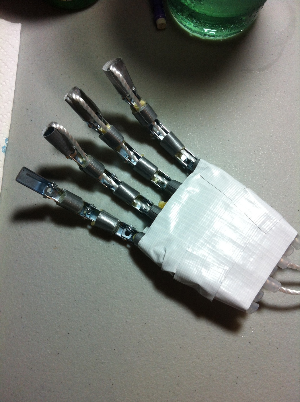
To close, here’s part of the hand that we plan to make the robot’s end affector:
The picture cuts it off, but here’s how it works: it’s rough anatomically correct, with all the joints where they’re supposed to be. As shown is the “default” state for the hand. There’s a string that’s fixed to the end of a finger, and it is fed through the inner of the finger (the “bones” are hollow rubber tubes). The hand part is also constructed of a series of hollow tubes encased in foam, so that there is a path from the fingertip to the bottom of the hand, where the other end of the string comes out. When the string is pulled, the finger bends, and when the string is released, the finger returns to the default state. The idea is to tie the end that comes out of the bottom of the hand to a motor, and correspond servo motor pulses to the degree of finger bend. Here’s a video describing what I mean:
(Cameron Reid featured in the video)
Well, I think that’s enough for one update. Look out for the next one where I will hopefully have the shoulder working.
Alright, just this class stands between me and my undergraduate degree: Senior Design. As my last post indicated, my project involves a robotic arm with a kinect interface. I am completing the project with the help of my group members Cameron Reid, Chris Stubel, and Carlton Beatty. Here is the brainstorm doodle from the last post:
The premise is pretty simple. You (the user) move your arm, and the system tracks your movements and projects it to a robotic arm, mimicking your actions in real time. Realistically, this can be used to introduce the human element where humans can’t safely go, such as bomb disposal, battle situations, disaster relief. Unrealistically? Well, maybe you’ve heard of a little movie recently called Pacific Rim…I think that would be pretty cool.
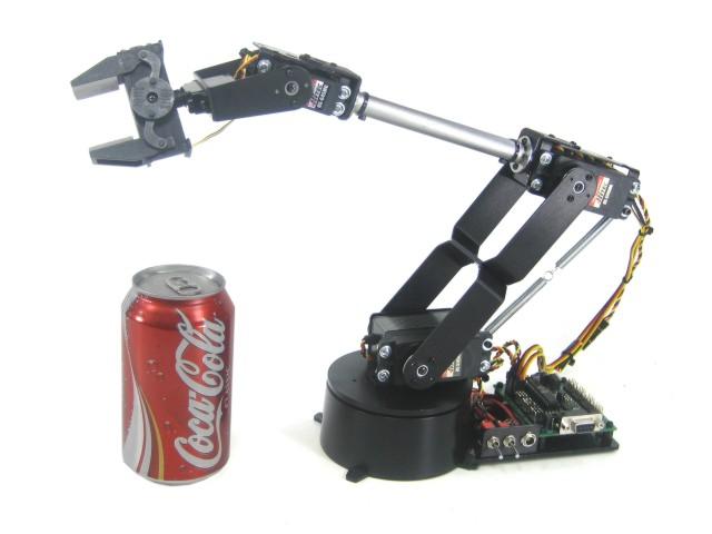
Our plan is to use a simple entry level robotic arm, such as this AL5D by Lynxmotion:
so as to avoid designing our own arm, which is more work than we want to do on the time restriction. We’ve got an arm to control, but what’s going to be doing the tracking? That’s where the Kinect comes in. The Kinect is a incredible piece of technology. It’s got sensors out the wazoo, and Microsoft has a great SDK that goes along with it so anybody can make apps utilizing the Kinect. In particular, they’ve got a skeletal tracking library, which will enable us to detect and retrieve skeleton joints in 3D space. We will get (at least) all the major joints on the arm: shoulder, elbow, wrist, and turn the coordinates into the angles that the limbs form. These angles will get transmitted to a microcontroller that control servos on the arm.
Now, look at the picture above, and look at what’s on the end. I want to take that simple claw, and instead put in its place an animatronic hand. By putting something more like a hand there, I’m hoping we can give this system more dexterity. Definitely not to the degree of our own hands, but at least more than the claw that the arm comes with. To accomplish this will take some creativity, since the Kinect tracking system we are using for the arm doesn’t have the resolution to track individual digits. We are going to construct a glove outfitted with flex sensors over the fingers. As a finger bends, the sensor reading is read by a microcontroller and the microcontroller in turn controls motors to move the fingers.
Here is the above in flow diagram form:
Like I said previously, this project is actually in progress already, so the next post will include the first update.
I’m excited to announce my senior capstone project: Robotic Arm with Kinect Interface (it’s a …working title). Let me show you my vision with this amateur sketch.
The idea is simple: to make a robotic limb mimic a human user’s arm. However, I won’t go into details in this post. The next posts will go into the project in more detail, as well as updates into the current progress. So excited!
Problem: Consider the picture below (image credits to Project Euler)
The four triangles are assumed to be right triangles. When placed in the arrangement as shown, there is a hole in the middle. Consider all right triangles that have perimeter less than 100,000,000, how many of the right triangles make a hole such that the hole can be used to tile the larger resulting square?
For any right triangle, let the smaller leg be “a”, the longer leg be “b”, and the hypotenuse “c”, so that any triangle can be identified by a tuple (a, b, c). It then follows that the hole is a square with side lengths (b-a). From the image, it also follows that the larger square has side lengths equal to the hypotenuse of the constituent triangles. For the larger square to be able to be tiled by the hole, its side lengths must then be an integer multiple of the hole’s side lengths, or put simply: c = (b-a)k, for some k. This would be a simple test, supposing that you could generate all pythagorean triples (a, b, c) such that the perimeter is within the bounds of the question.
Given the problem parameters, it wouldn’t be prudent to iterate blindly over “a”, “b”, and “c” to generate the triples. The easiest way I know how is by Euclid’s formula (http://en.wikipedia.org/wiki/Pythagorean_triple#Generating_a_triple). For any pair (m, n), the following are always a Pythagorean triple:
a = m^2 – n^2
b = 2mn
c = m^2 + n^2
You can compute a^2 + b^2 = c^2 to see for yourself. Moreover, this formula is complete, in the sense that you can generate all primitive Pythagorean triples with this, primitive triples being (a, b, c) such that the greatest common divisor of the triple is 1. The triple is guaranteed to be primitive as long as (m, n) are coprime and of opposite parity. Lastly, as we all know, given a Pythagorean triples, the same multiple of each length is also a Pythagorean triple. Armed with this, we can generate all triples.
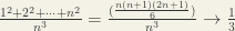
To make sure that that each primitive we generate is unique, assume that m > n. This also reduces the number of times we have to iterate considerably. Again, the process we’ll go through generates primitive triples, but it is a simple matter to calculate how many similar triangles also fit the perimeter bound, simply by dividing 100000000 by the primitive triple’s perimeter.
Consider the quantity when divided by a^2. The remainder is a function of n, and attains a max for certain values of n. Call the maximal remainder r_max. Compute the sum of r_max over the range of 3<=a<=1000.
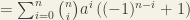
I had a lot of fun with this one, especially because unlike the other problems, it could be done without programming. There’s a lot of math, and it culminates in a simple formula for the answer. Well, ok, not so simple, but you could plug it into a calculator or WolframAlpha. Using the binomial theorem, we get
From this we immediately see that the half the terms are 0, which could have also been obvious since (a-1)^n will expand with alternating signs. But there is a larger insight: For all terms in which i >= 2, all have a nonzero integer quotient when divided by a^2, as evident from the presence of the a^i factor. Of the two surviving terms, as from the beginning of this paragraph, one is 0, thus
, if n is even and
, if n is odd
In the range of “a” considered for the problem, any odd n produces a remainder larger than 2 when divided by a^2. Thus, it will not behoove us to consider even n. Our solution will consist of finding n so that 2na is as close possible to a^2, but not exceeding it. So consider the inequality 2na < a^2, or 2n < a. It will again be beneficial to consider the case of odds and evens.
If a is even, the value of n that satisfies the inequality is n = a/2 – 1, and the corresponding remainder is a^2 – 2a. (*)
If a is odd, the value of n that satisfies the inequality is n = (a-1)/2, and the corresponding remainder is a^2 – a. (**)
And that’s it! If we sum the expression (*) over the evens, and the expression (**) over the odds, in the range 3<=a<=1000, it will provide the answer, which is 333082500.
As an added bonus, let’s produce a more direct formula:
Such an expression you can just plug into a calculator to get the same result.
Perhaps you’ve seen them, those displays that use light emitting diodes (LEDs) to illuminate some kind of graphic or message. Commonly seen at stadiums, stock exchanges, on top of buses, etc. Well, it’s really easy to make one of your own, which is the goal of this project. Here’s version 1:
Of course, it doesn’t have the resolution of commercially made ones – this one only measures 8 LEDs x 8 LEDs. You can still do some interesting things with it.
So how does it work? We’ll illustrate the principle by taking a small subset of the display, say a 3×3 portion:
How would you control this? Well you could say that you’ll simply connect each LED to an IO pin on your controller. So it would take 9 IO pins to drive just that portion of the display. Sure, that’s well and good for this example, but as soon as this project gets any bigger, you’ll realize you’ll quickly run out of pins. The Atmega328p has 13 digital out pins, clearly not enough for my 8×8 display, so how can we get around this? What if we let each row and each column be connected to a pin, something like this (and let’s make it more official looking):
How this will work is that when a column pin is ON, it will source current to that entire column. When a row pin is ON, it will allow that row to sink current (how it will do this will be explained in the schematic later). This is called multiplexing. If you give this a coordinate system, turning on a particular (row, column) pin combination completes the circuit at location (row, column) on the display.
Note that in this configuration, you can light a selection of LEDS on a particular row by turning on the respective columns, and turning on that row, OR you can light a selection of LEDS on a particular row by turning on the respective rows, and turning on that column, but you could not do both. At least not at the same time. It will also be hard to drive an entire column from one pin, since that means sourcing current an entire column. Suppose a maximum of 20mA per LED, a pin must somehow supply 20×3 = 60mA for a column, so we’ll want to avoid this.
Because a pin either sinks an entire row or sources an entire column, there is no way to simultaneously reference multiple rows and multiple columns, but what if we could make it LOOK like it? Here’s the basic idea: Since you can’t drive the display as a whole, you can at best drive parts of it. We’ll assume that you drive multiple columns at a time, and only sink one row at a time. In our first image, we turn on columns 1 and 3, and we turn on row 1. Some split second later, we turn on column 2 and row 2. Yet another split second later, we turn on column 1 and 3 again, but row 3 this time. We repeat this many, many times, and if you do this fast enough, it will appear as if you are looking at the fourth image, though if you grab an oscilloscope or increase the delay, you’ll see this is clearly not the case. This is a result of a phenomenon called persistence of vision (http://en.wikipedia.org/wiki/Persistence_of_vision). In short, our eyes are not a perfect analog device. An image could last for a brief moment on our retinas. If the moment an LED is off is imperceptible to us, it will appear as if we are looking at the display as a whole.
The actual construction of the display isn’t very difficult. Here is a circuit schematic:
You’ll notice in addition to the uC (an ATmega328p) there are two shift registers. Shift registers are an excellent option for increasing the number of IO pins on your controller. At a cost of a little delay, you can effectively drive 8 outputs with 3 pins. Each register controls a column/row set.
* I had to make a change to my schematic post construction. Each register has 8 outputs, QA through QH. The original schematic mapped the top register’s output like this:
output | H | G | F | E | D | C | B | A
column | 1 | 2 | 3 | 4 | 5 | 6 | 7 | 8
I did not pay attention when I was soldering, and I soldered the wrong columns to the wrong outputs. This is reflected on the diagram. It’s of minor consequence, but the original reason for the above mapping is so that you could write a function that would take 8 binary bits that directly correspond to the which columns you wanted on, and each digit would correspond to a column, e.g 10010011 means columns 1, 4, 7, and 8 are on. The mistake requires a software fix.
As for the registers that control the rows. A register pin can’t sink much more than ~35mA of current, so each pin routes each row to ground through a 3904 transistor. When a row register pin is high, it turns on the transistor and opens a path to ground. In software, the row register does nothing but repeatedly cycle through the rows 1-8. Another way to achieve this is through an IC called a decade counter, which has 10 pins, only 1 of which will be on at a time.
An 8×8 display is rather limiting, so this isn’t much good for anything other than a learning experience. I plan to make another one, at least several characters in length, more appropriate for a marquee. It will incorporate some user input so you could play some games on it, and FTDI so any user could send it a character string to display. I had fun with this, I hope people find this interesting as well.
They caught us using desktops (which sort of goes against the “Embedded” part of ECE4180 – Embedded Systems), but that’s only because of the time constraint. Still though, I’m glad for the feature. Thanks Hackaday!
This is a problem I had on my Math4318 – Analysis II final last Thursday:
We were also given this hint: “Think about Riemann sums”, but I had no idea what to do with it. I scribbled down a generalized Riemann sum and thought nothing of it.
where is the length of a subset of a partition (the “width” of the rectangles) and is some value in the same subset of the partition.
A final exam period lasts for about 3 hours. After I finished most of the other problems, which I took about an hour, I stared at this one blankly for a good half hour, making scribbles and random calculations until I saw the solution. Maybe it was the lack of sleep, or just one of those moments where you just don’t see it, but I just didn’t get it immediately. Shame. But before we get to the solution, some observations:
, so that the limit should be less than one. Just in case we arrive at what we think is a final solution, this can be a the first check.
Trying the expression for specific value of k’s. It’s going to depend on how much background knowledge you have. Notice that if
k=1, then we have:
k=2, then we have:
k=3, and this one’s a stretch of the mind to remember, I sure didn’t on the exam, but I will include it here anyways:
If the exam taker didn’t remember those special summation formulas, they aren’t necessary to arrive at the answer. But I at least had the first 2, and it’s not too much of a stretch to guess the answer: 1/(k+1). This would have been greatly reinforced with the knowledge of k=3.
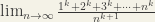
To get the final solution, we return to the hint: Riemann sums. Usually, given a continuous function to estimate the integral of, one uses a constant mesh size. Specifically, if n is the number of partitions we are using, and “a” and “b” are the left and right endpoints of the integral, respectively, then the mesh size is (b-a)/n. What if a = 0, and b = 1? Then we have (b-a)/n = 1/n. Then with a little rewriting:
Then we can see the expression we were given in the beginning was really a Riemann sum for the integral of x^k over the interval [0,1], using a constant mesh size over n subintervals, where the approximation rule was to use the right endpoint of the intervals. (To see this, list the points of the partiiton: {0, 1/n, 2/n, 3/n, … , n/n = 1}).
Then as in the classical explanation of integrals to first year university students, if this is an approximation for an integral, as we let the “rectangles” get smaller and smaller (that is, let n approach infinity, so 1/n approaches 0), the approximation gets better and better, ideally approaching the integral itself. In other words,
which fortunately agrees with our conjecture earlier.
As of now, CarlsenBot v1 is completed. It just went through the final presentation with flying colors, I’m happy to report. This post will detail the project, my findings, possible future plans, etc…
Here is this post in video form:
About
It’s a gargantuan thing
CarlsenBot is my team’s final project for ECE4180 Embedded Systems at Georgia Tech.
CarlsenBot was built by me and my teammates: Anthony Trakowski, Daniel Paul Martin, and James Flohr. Since I had the idea for the project, I assumed the managerial role. CarlsenBot is a voice activated chess playing robot. It’s exactly what it sounds like: user (or users) can say the chess move they want to make, and the robot realizes them (the idea is to emulate “Wizard’s Chess“, from Harry Potter lore). For a sample, check out the video below:
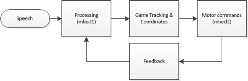
Overview
A highly simplified project flow diagram is above. **There is a slight typo: “mbed1” and “mbed2” should just be “mbed”. Mbed (www.mbed.org) is the microcontroller platform we are using. It has a lot of support, and is the microcontroller used for the majority of this class.
The major components are: a speech processing unit for recognizing commands, a game tracking unit that does everything related to the actual chess game, and a robot control unit, that controls all the hardware. These are discussed in detail next.
Voice Recognition
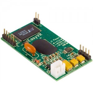
As mentioned above, the idea was to emulate Wizard’s Chess. Users would use the usual chess jargon, i.e. “Knight to e4”, to indicate a move. The problem would occur when that choice leads to an ambiguity, if say, two knights could both move to e4. Because of this, we indicate moves by indicating both a start AND destination square, e.g. “f3 to e4”. This would lead to yet another problem, where two letters could potentially sound the same, such as “b” and “d”, making speech recognition difficult. This was circumvented by using the Navy phonetic alphabet (‘a’ = “alpha”, ‘b’ = “bravo”, etc…). Future revisions may include work to make this sound more natural, and more alike to the standard chess move notation. For now, moves are recognized by saying a letter, number, letter, and number in succession, with the assumption the first number-letter pair are the source square, and the latter half the destination square. With the standards set, we set upon finding a suitable voice recognition platform. We ultimately found a hardware solution in EasyVR (below).
Microphone not shown
EasyVR can be programmed to recognize both trained and untrained words, though obviously to a limited capacity, but it should be enough for four users. Prior to usage, each user needs to have trained the first 8 phonetic alphabet letters. For reference, they are:
Alpha
Bravo
Charlie
Delta
Echo
Foxtrot
Golf
Hotel
These reference columns on the chess board. EasyVR comes preprogrammed with SPEAKER INDEPENDENT recognition for the numbers 0-9. Only 1-8 is used for referencing chessboard rows.
**EasyVR is very sensitive to noise. It’s important that if the reader intends to replicate this project and continue using EasyVR, to be in a suitable (read: quiet) working environment.
Once all four parameters are recognized, it is passed serially to a desktop containing the next unit of our project…
Chess Game
A desktop nearby is running a chess engine called “chess-at-nite” (thanks to the creators). The engine does all the functions related to the game itself, such as keeping track of turns, detecting checks/mates, and most importantly, validating moves. We had to modify it to accept serial data coming from the mbed (well, James did). The serial data is just a four-character (letter-number-letter-number) string with the intended move. If it is indeed valid, it gives the OK for the robot to make the necessary hardware movements. It does this by passing back the string to the mbed. If the move is not valid, the recognized parameters are nulled, and the current turn begins anew. Here’s an example of the program output:
(Little does it know I’m setting a trap for it…)
* Thanks to James and Tony for going above and beyond what I had in mind. It was my intention to write our own validation function. Moreover, I had only intended for this to be player vs. player, but this engine allows a player to play against a computer. It’s easily in my opinion the coolest part of this project: to play against a computer in a physical sense.
** The link above is the original, bare engine, and does not contain our modifications. Please email me, Ben Yeh at ben.p.yeh@gmail.com for our changes. I will also put it up on my github in due time.
Movement
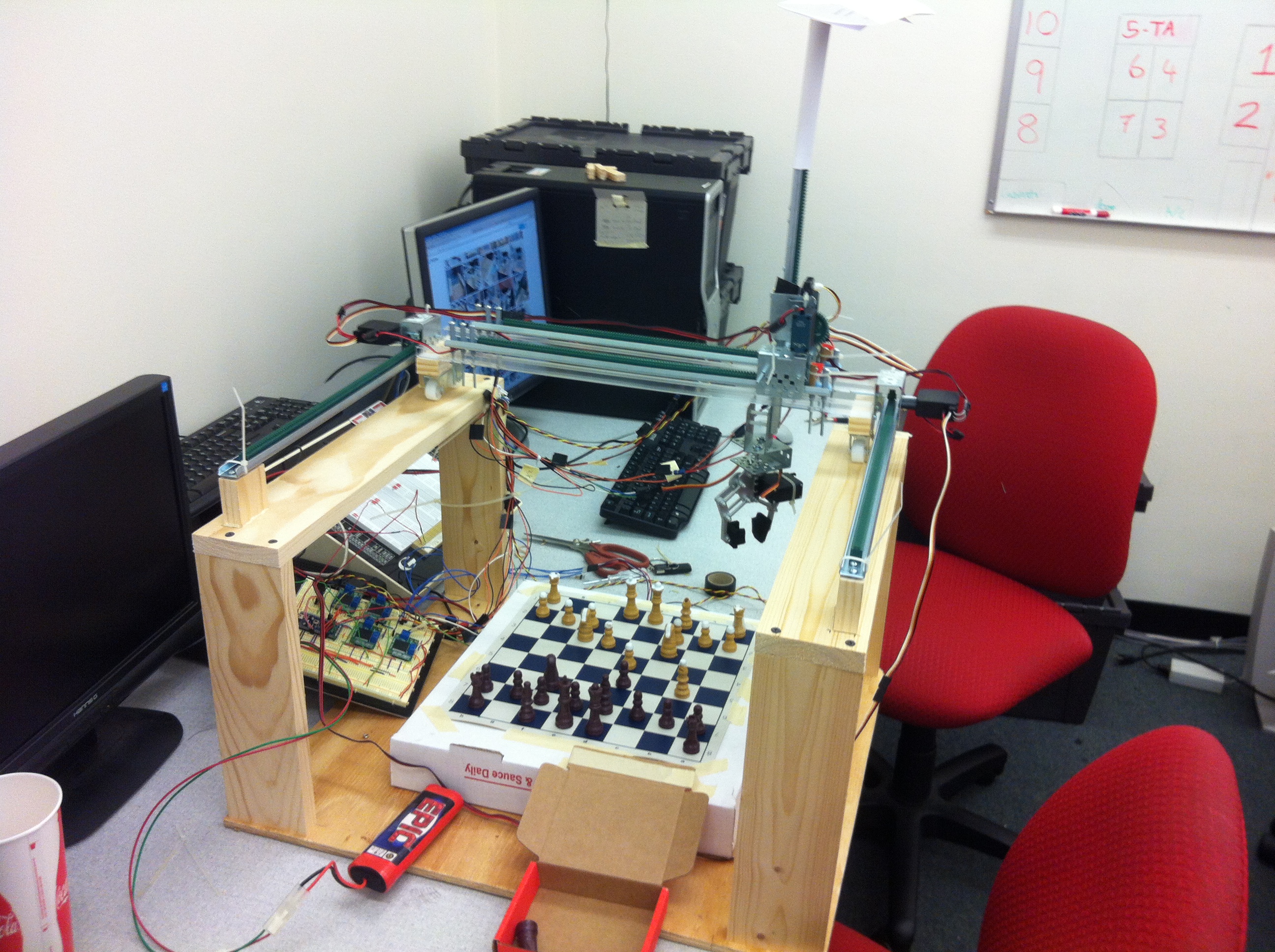
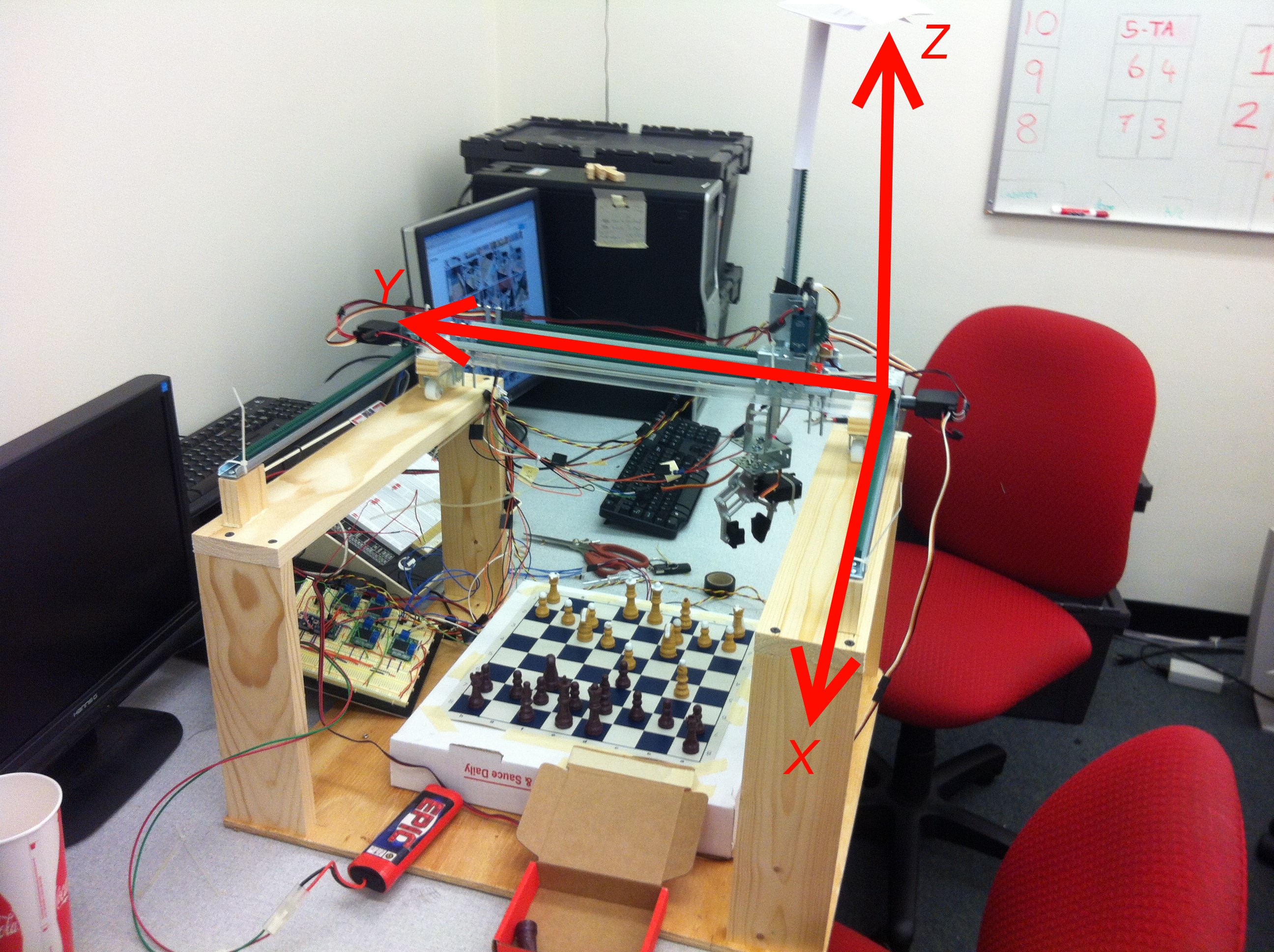
Here is my contribution: Paul (Daniel) and I built this “robot”, having no prior mechanical engineering experience. Go us.
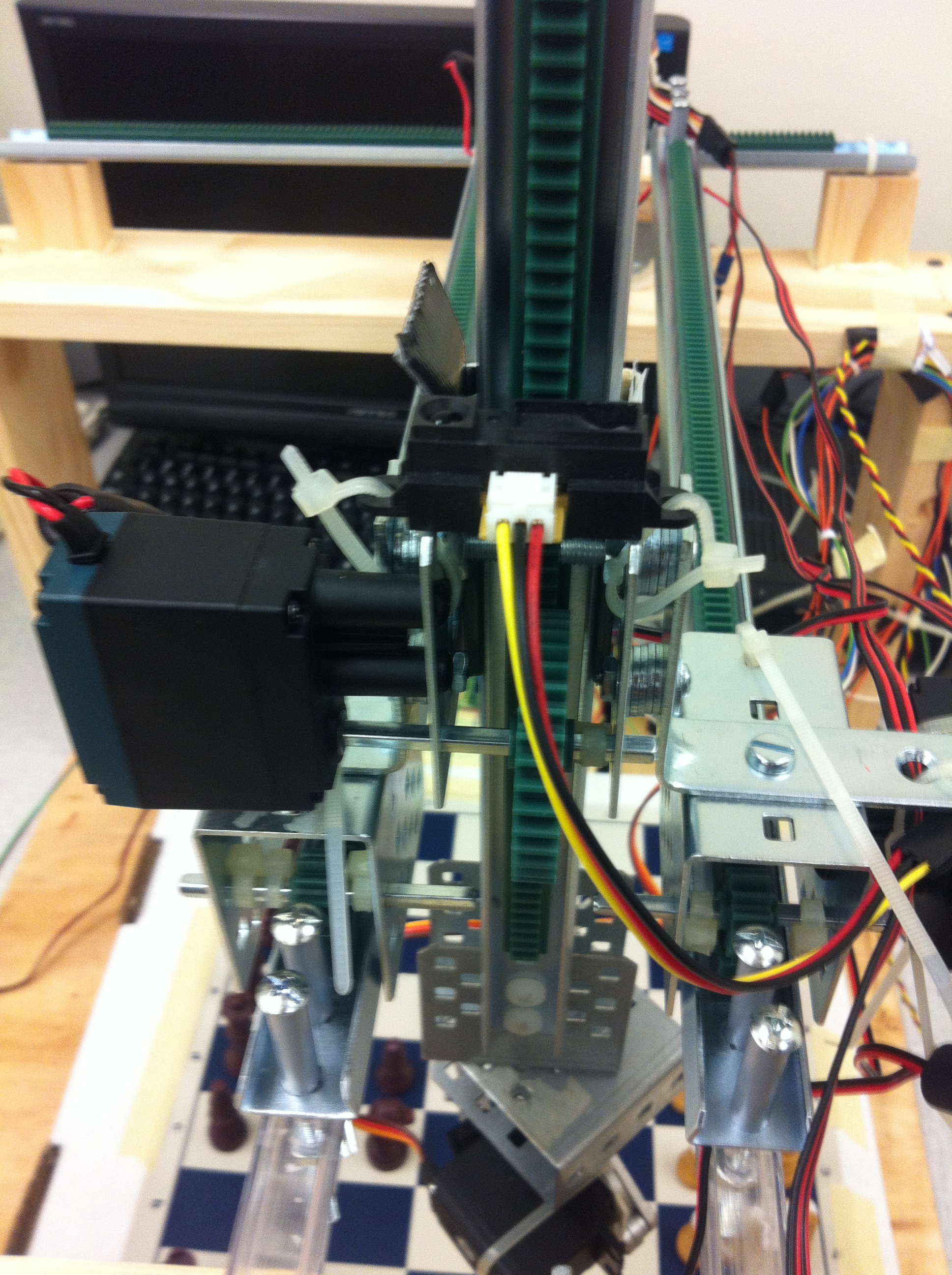
Look in the picture above for the standard axis orientations. For the sheer span, two motors are needed to realize movement in the x axis. Here are the motors and a close up picture of how they move:
When the X motors turn, the gear translates the rotational movement into linear movement (the technical term for the setup is a pinion (the gear) and rack (toothed rails)). When they move, they carry the platform in between them along the x axis. Resting on the Y axis is a similar setup to the X axis, just in a smaller scale. Because of this, it only requires one motor.
Here’s a closeup of the platform in between X motors, on which this travels:
Wire management leaves something to be desired
Lastly, sandwiched between the double rails is the section for the Z motor to rest on:
In this picture, the double rails are the Y axis, and the motor on the left controls the z axis. Unlike the X and Y axis, which moves with respect to a fixed rack, the Z axis motor is fixed, and moves the arm up and down.
This picture deserves some explanation. Our rig uses simple DC motors from Vex to turn the gears. Vex also produces these encoders as separate I2C devices that attach to the back of the motors. The encoders are quadrature encoders that will allow us to poll them to determine the current position. All motors are identical (with the exception of the Y axis motor, which is just slightly more powerful), so they can all be affixed with the same encoder. It was an oversight on my part to not buy enough. With more time, we would have waited until we bought another, but we received all the parts with about a week and half to finish the project. Instead, we opted for using a distance sensor, shown above. The distance sensor is fixed on the Z axis bracket, and senses the distance between it and this variable barrier:
MacGyver would be proud. (That’s Paul in the picture)
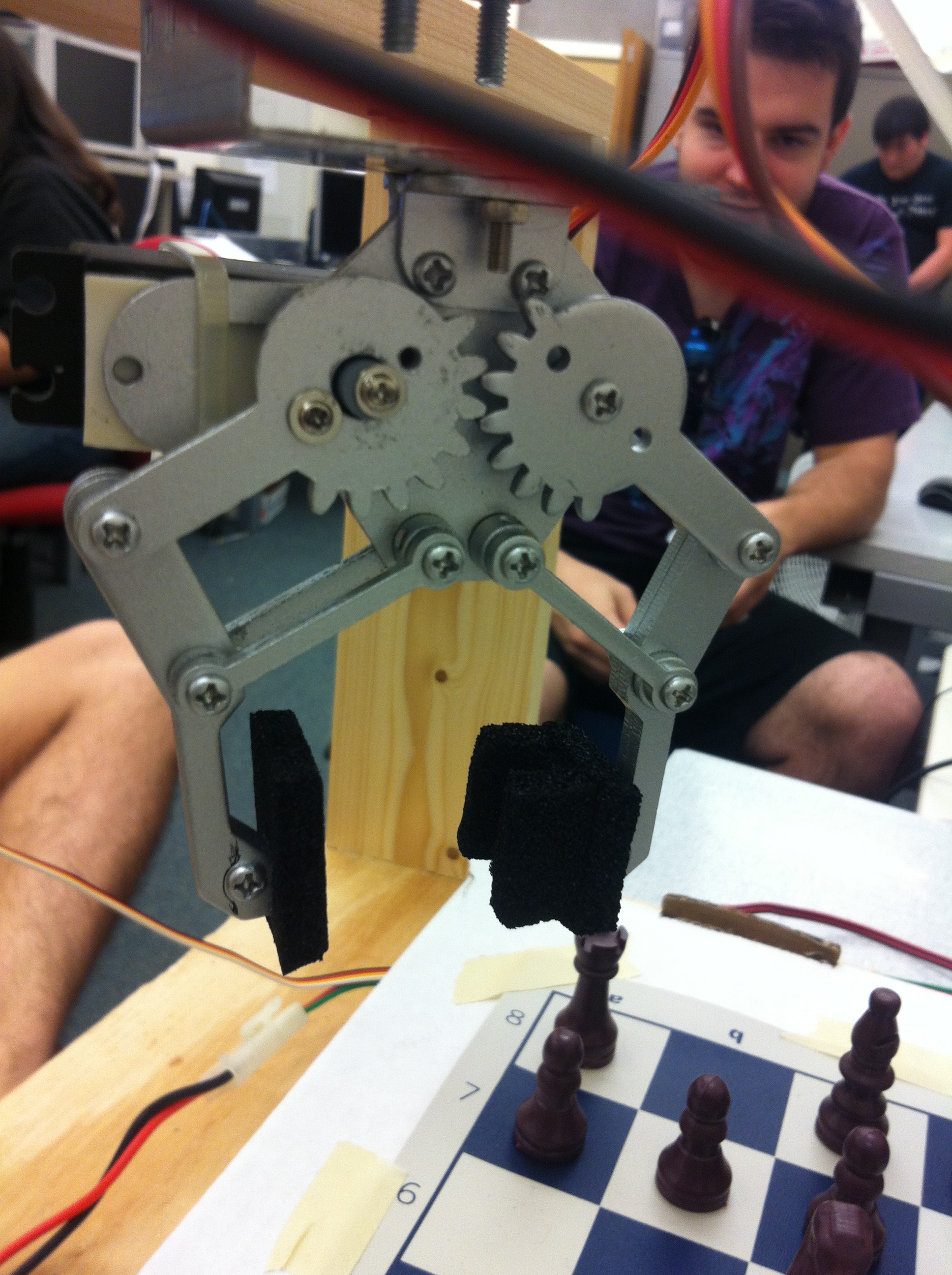
On the other end of the Z axis arm is the claw:
We glued some foam pieces onto the end, so as to allow us to grab pieces more easily. The claw is controlled by a servo motor, with only two set positions in code: OPEN and CLOSE. When X, Y, and Z are done moving, the claw is then free to grip or release a piece.
As mentioned, the encoders on the motor is important, since it provides feedback. PID loops control all the motors (well, actually just PI in the case). I couldn’t quite tune it to get what I wanted to happen, so a fix is that the motors just get “close enough”, and then moves with the minimum speed to its destination. You may see this in some of the videos: the rig moves with variable speed towards its destination, stops, and crawls for some small amount. This has successfully fixed overshoots without too much delay.
When the current move is done, the engine updates the game, and CarlsenBot waits for the next move.
Hope you’ve enjoyed reading. Please email me at ben.p.yeh@gmail.com if you have any questions.
Here are some more videos:
https://www.youtube.com/watch?v=M3mgB6fCdAE (This video shows what happens in a checkmate. It’s not as dramatic as I’d like it to be. If you pause at the end where show the terminal results, a line that says “…mate!” is printed at the top.
We finally got this moving towards the end of the day yesterday. It needs some fine-tuning, and integration with the other part of the project: the voice control, which my other teammates have been working on in parallel. Be looking for that in another post soon!
 The picture cuts it off, but here’s how it works: it’s rough anatomically correct, with all the joints where they’re supposed to be. As shown is the “default” state for the hand. There’s a string that’s fixed to the end of a finger, and it is fed through the inner of the finger (the “bones” are hollow rubber tubes). The hand part is also constructed of a series of hollow tubes encased in foam, so that there is a path from the fingertip to the bottom of the hand, where the other end of the string comes out. When the string is pulled, the finger bends, and when the string is released, the finger returns to the default state. The idea is to tie the end that comes out of the bottom of the hand to a motor, and correspond servo motor pulses to the degree of finger bend. Here’s a video describing what I mean:
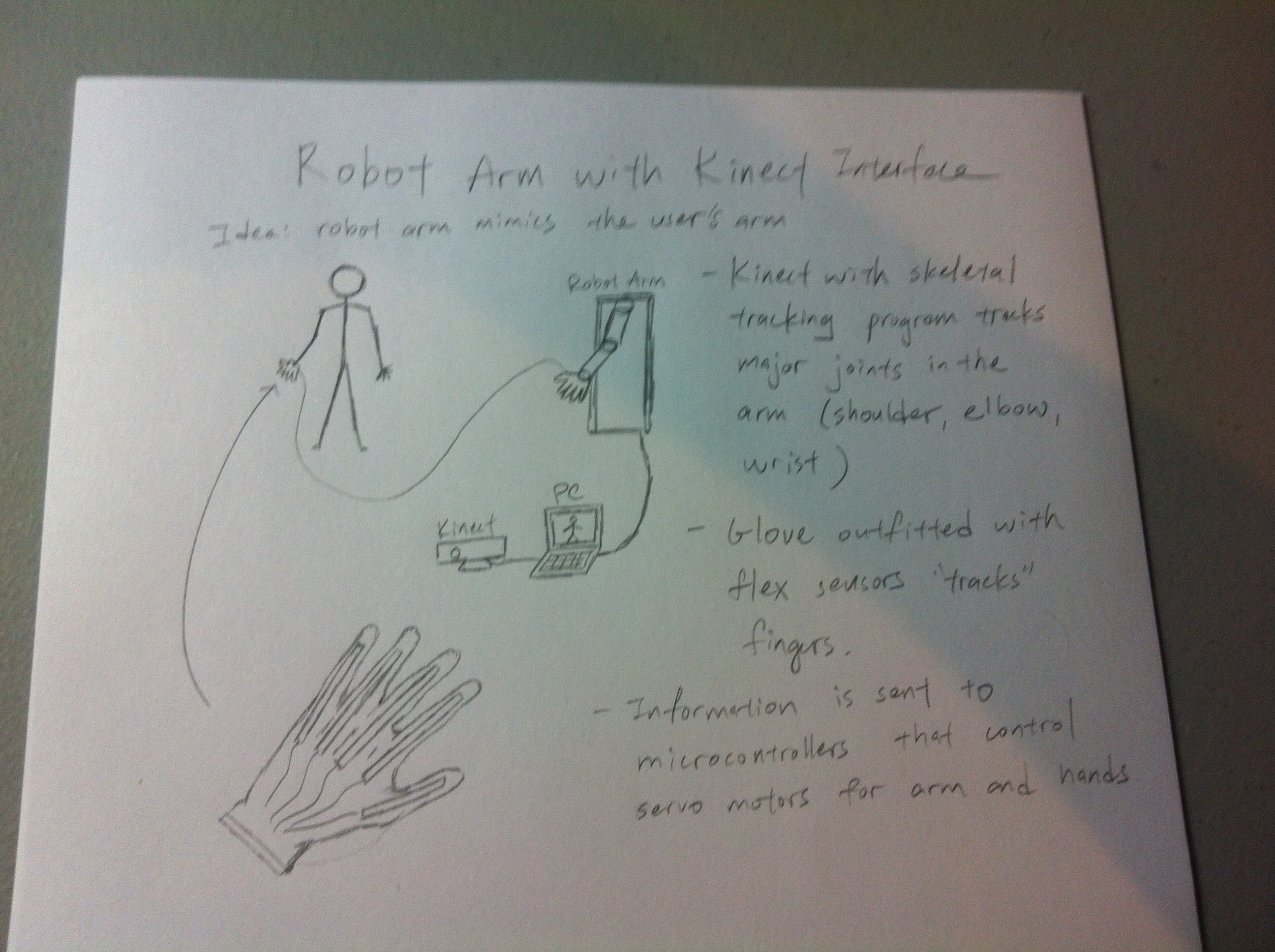


 when divided by a^2. The remainder is a function of n, and attains a max for certain values of n. Call the maximal remainder r_max. Compute the sum of r_max over the range of 3<=a<=1000.
 , if n is even and
 , if n is odd

![= \left[\sum_{i=1}^{1000}a^{2}\hspace{1mm}-(1+4)\right]- \sum_{i=3}^{1000}a\hspace{1mm}-2\sum_{i=2}^{500}a](https://s0.wp.com/latex.php?latex=%3D+%5Cleft%5B%5Csum_%7Bi%3D1%7D%5E%7B1000%7Da%5E%7B2%7D%5Chspace%7B1mm%7D-%281%2B4%29%5Cright%5D-+%5Csum_%7Bi%3D3%7D%5E%7B1000%7Da%5Chspace%7B1mm%7D-2%5Csum_%7Bi%3D2%7D%5E%7B500%7Da+&bg=f4f2e7&fg=333333&s=0&c=20201002)
![= \left[\frac{1000(1001)(2001)}{6}-5\right]-\frac{998(1003)}{2}-2\frac{499(502)}{2}](https://s0.wp.com/latex.php?latex=%3D+%5Cleft%5B%5Cfrac%7B1000%281001%29%282001%29%7D%7B6%7D-5%5Cright%5D-%5Cfrac%7B998%281003%29%7D%7B2%7D-2%5Cfrac%7B499%28502%29%7D%7B2%7D+&bg=f4f2e7&fg=333333&s=0&c=20201002)


 is the length of a subset of a partition (the “width” of the rectangles) and
  is some value in the same subset of the partition.
 , so that the limit should be less than one. Just in case we arrive at what we think is a final solution, this can be a the first check.

![\frac{1^k+2^k+\cdots+n^k}{n^{k+1}} = \frac{1}{n}\left [ \left(\frac{1}{n}\right)^k + \left(\frac{2}{n}\right)^k + \cdots + \left(\frac{n}{n}\right)^k \right ]](https://s0.wp.com/latex.php?latex=%5Cfrac%7B1%5Ek%2B2%5Ek%2B%5Ccdots%2Bn%5Ek%7D%7Bn%5E%7Bk%2B1%7D%7D+%3D+%5Cfrac%7B1%7D%7Bn%7D%5Cleft+%5B+%5Cleft%28%5Cfrac%7B1%7D%7Bn%7D%5Cright%29%5Ek+%2B+%5Cleft%28%5Cfrac%7B2%7D%7Bn%7D%5Cright%29%5Ek+%2B+%5Ccdots+%2B+%5Cleft%28%5Cfrac%7Bn%7D%7Bn%7D%5Cright%29%5Ek+%5Cright+%5D+&bg=f4f2e7&fg=333333&s=0&c=20201002)