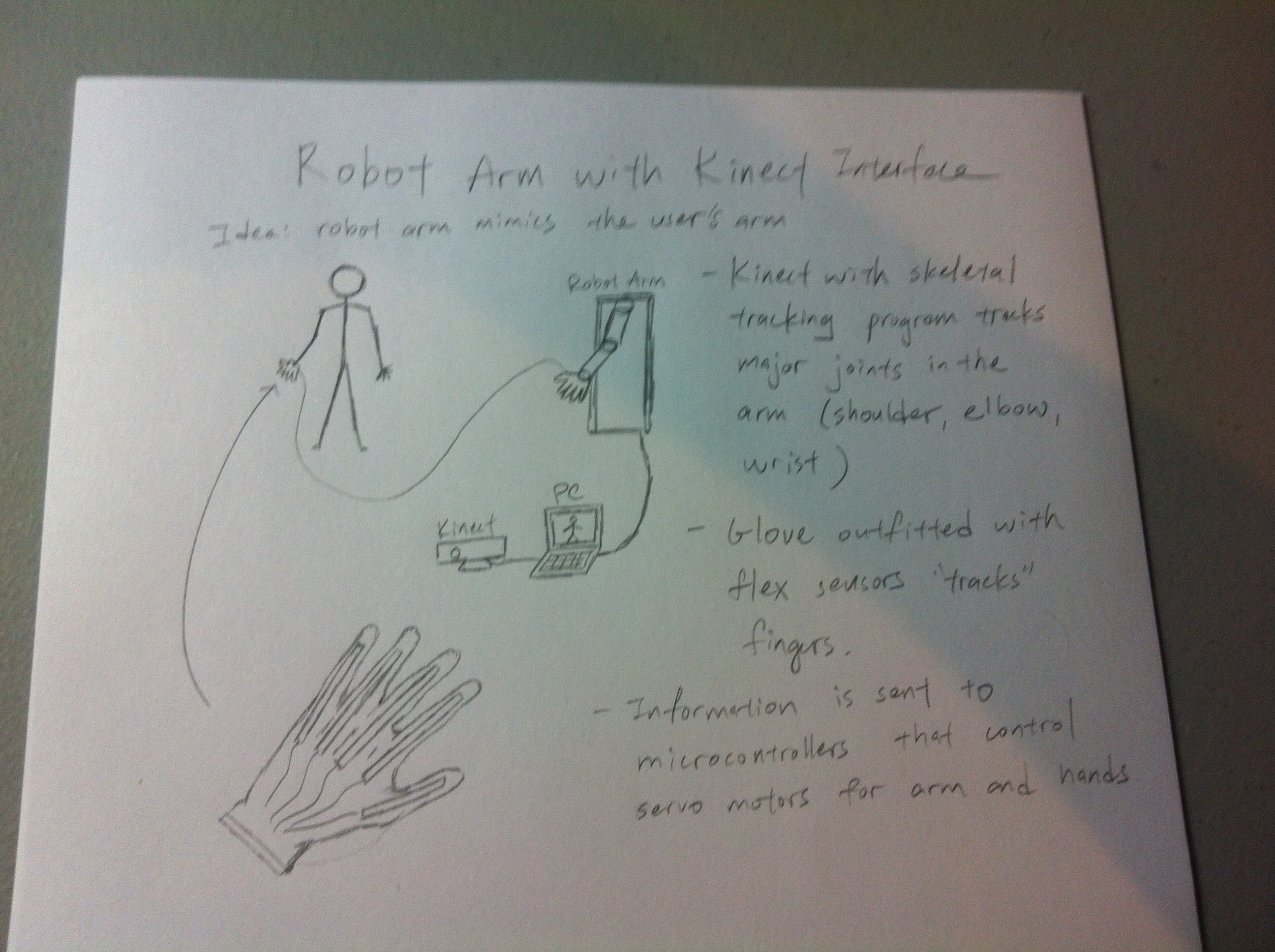
I’m excited to announce my senior capstone project: Robotic Arm with Kinect Interface (it’s a …working title). Let me show you my vision with this amateur sketch.
The idea is simple: to make a robotic limb mimic a human user’s arm. However, I won’t go into details in this post. The next posts will go into the project in more detail, as well as updates into the current progress. So excited!
Perhaps you’ve seen them, those displays that use light emitting diodes (LEDs) to illuminate some kind of graphic or message. Commonly seen at stadiums, stock exchanges, on top of buses, etc. Well, it’s really easy to make one of your own, which is the goal of this project. Here’s version 1:
Of course, it doesn’t have the resolution of commercially made ones – this one only measures 8 LEDs x 8 LEDs. You can still do some interesting things with it.
So how does it work? We’ll illustrate the principle by taking a small subset of the display, say a 3×3 portion:
How would you control this? Well you could say that you’ll simply connect each LED to an IO pin on your controller. So it would take 9 IO pins to drive just that portion of the display. Sure, that’s well and good for this example, but as soon as this project gets any bigger, you’ll realize you’ll quickly run out of pins. The Atmega328p has 13 digital out pins, clearly not enough for my 8×8 display, so how can we get around this? What if we let each row and each column be connected to a pin, something like this (and let’s make it more official looking):
How this will work is that when a column pin is ON, it will source current to that entire column. When a row pin is ON, it will allow that row to sink current (how it will do this will be explained in the schematic later). This is called multiplexing. If you give this a coordinate system, turning on a particular (row, column) pin combination completes the circuit at location (row, column) on the display.
Note that in this configuration, you can light a selection of LEDS on a particular row by turning on the respective columns, and turning on that row, OR you can light a selection of LEDS on a particular row by turning on the respective rows, and turning on that column, but you could not do both. At least not at the same time. It will also be hard to drive an entire column from one pin, since that means sourcing current an entire column. Suppose a maximum of 20mA per LED, a pin must somehow supply 20×3 = 60mA for a column, so we’ll want to avoid this.
Because a pin either sinks an entire row or sources an entire column, there is no way to simultaneously reference multiple rows and multiple columns, but what if we could make it LOOK like it? Here’s the basic idea: Since you can’t drive the display as a whole, you can at best drive parts of it. We’ll assume that you drive multiple columns at a time, and only sink one row at a time. In our first image, we turn on columns 1 and 3, and we turn on row 1. Some split second later, we turn on column 2 and row 2. Yet another split second later, we turn on column 1 and 3 again, but row 3 this time. We repeat this many, many times, and if you do this fast enough, it will appear as if you are looking at the fourth image, though if you grab an oscilloscope or increase the delay, you’ll see this is clearly not the case. This is a result of a phenomenon called persistence of vision (http://en.wikipedia.org/wiki/Persistence_of_vision). In short, our eyes are not a perfect analog device. An image could last for a brief moment on our retinas. If the moment an LED is off is imperceptible to us, it will appear as if we are looking at the display as a whole.
The actual construction of the display isn’t very difficult. Here is a circuit schematic:
You’ll notice in addition to the uC (an ATmega328p) there are two shift registers. Shift registers are an excellent option for increasing the number of IO pins on your controller. At a cost of a little delay, you can effectively drive 8 outputs with 3 pins. Each register controls a column/row set.
* I had to make a change to my schematic post construction. Each register has 8 outputs, QA through QH. The original schematic mapped the top register’s output like this:
output | H | G | F | E | D | C | B | A
column | 1 | 2 | 3 | 4 | 5 | 6 | 7 | 8
I did not pay attention when I was soldering, and I soldered the wrong columns to the wrong outputs. This is reflected on the diagram. It’s of minor consequence, but the original reason for the above mapping is so that you could write a function that would take 8 binary bits that directly correspond to the which columns you wanted on, and each digit would correspond to a column, e.g 10010011 means columns 1, 4, 7, and 8 are on. The mistake requires a software fix.
As for the registers that control the rows. A register pin can’t sink much more than ~35mA of current, so each pin routes each row to ground through a 3904 transistor. When a row register pin is high, it turns on the transistor and opens a path to ground. In software, the row register does nothing but repeatedly cycle through the rows 1-8. Another way to achieve this is through an IC called a decade counter, which has 10 pins, only 1 of which will be on at a time.
An 8×8 display is rather limiting, so this isn’t much good for anything other than a learning experience. I plan to make another one, at least several characters in length, more appropriate for a marquee. It will incorporate some user input so you could play some games on it, and FTDI so any user could send it a character string to display. I had fun with this, I hope people find this interesting as well.
As of now, CarlsenBot v1 is completed. It just went through the final presentation with flying colors, I’m happy to report. This post will detail the project, my findings, possible future plans, etc…
Here is this post in video form:
About
It’s a gargantuan thing
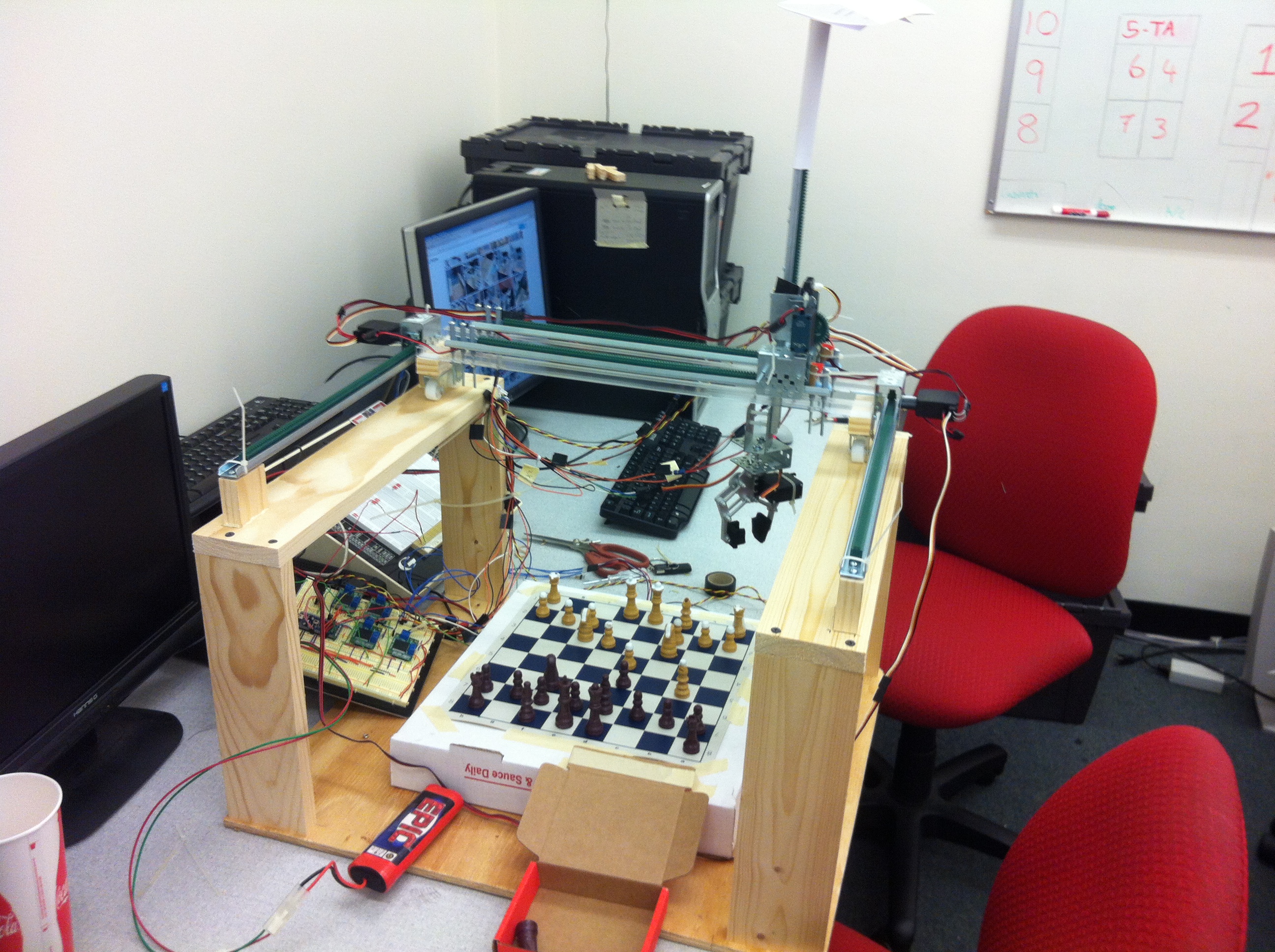
CarlsenBot is my team’s final project for ECE4180 Embedded Systems at Georgia Tech.
CarlsenBot was built by me and my teammates: Anthony Trakowski, Daniel Paul Martin, and James Flohr. Since I had the idea for the project, I assumed the managerial role. CarlsenBot is a voice activated chess playing robot. It’s exactly what it sounds like: user (or users) can say the chess move they want to make, and the robot realizes them (the idea is to emulate “Wizard’s Chess“, from Harry Potter lore). For a sample, check out the video below:
Overview
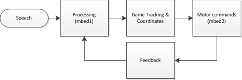
A highly simplified project flow diagram is above. **There is a slight typo: “mbed1” and “mbed2” should just be “mbed”. Mbed (www.mbed.org) is the microcontroller platform we are using. It has a lot of support, and is the microcontroller used for the majority of this class.
The major components are: a speech processing unit for recognizing commands, a game tracking unit that does everything related to the actual chess game, and a robot control unit, that controls all the hardware. These are discussed in detail next.
Voice Recognition
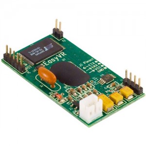
As mentioned above, the idea was to emulate Wizard’s Chess. Users would use the usual chess jargon, i.e. “Knight to e4”, to indicate a move. The problem would occur when that choice leads to an ambiguity, if say, two knights could both move to e4. Because of this, we indicate moves by indicating both a start AND destination square, e.g. “f3 to e4”. This would lead to yet another problem, where two letters could potentially sound the same, such as “b” and “d”, making speech recognition difficult. This was circumvented by using the Navy phonetic alphabet (‘a’ = “alpha”, ‘b’ = “bravo”, etc…). Future revisions may include work to make this sound more natural, and more alike to the standard chess move notation. For now, moves are recognized by saying a letter, number, letter, and number in succession, with the assumption the first number-letter pair are the source square, and the latter half the destination square. With the standards set, we set upon finding a suitable voice recognition platform. We ultimately found a hardware solution in EasyVR (below).
Microphone not shown
EasyVR can be programmed to recognize both trained and untrained words, though obviously to a limited capacity, but it should be enough for four users. Prior to usage, each user needs to have trained the first 8 phonetic alphabet letters. For reference, they are:
Alpha
Bravo
Charlie
Delta
Echo
Foxtrot
Golf
Hotel
These reference columns on the chess board. EasyVR comes preprogrammed with SPEAKER INDEPENDENT recognition for the numbers 0-9. Only 1-8 is used for referencing chessboard rows.
**EasyVR is very sensitive to noise. It’s important that if the reader intends to replicate this project and continue using EasyVR, to be in a suitable (read: quiet) working environment.
Once all four parameters are recognized, it is passed serially to a desktop containing the next unit of our project…
Chess Game
A desktop nearby is running a chess engine called “chess-at-nite” (thanks to the creators). The engine does all the functions related to the game itself, such as keeping track of turns, detecting checks/mates, and most importantly, validating moves. We had to modify it to accept serial data coming from the mbed (well, James did). The serial data is just a four-character (letter-number-letter-number) string with the intended move. If it is indeed valid, it gives the OK for the robot to make the necessary hardware movements. It does this by passing back the string to the mbed. If the move is not valid, the recognized parameters are nulled, and the current turn begins anew. Here’s an example of the program output:
(Little does it know I’m setting a trap for it…)
* Thanks to James and Tony for going above and beyond what I had in mind. It was my intention to write our own validation function. Moreover, I had only intended for this to be player vs. player, but this engine allows a player to play against a computer. It’s easily in my opinion the coolest part of this project: to play against a computer in a physical sense.
** The link above is the original, bare engine, and does not contain our modifications. Please email me, Ben Yeh at ben.p.yeh@gmail.com for our changes. I will also put it up on my github in due time.
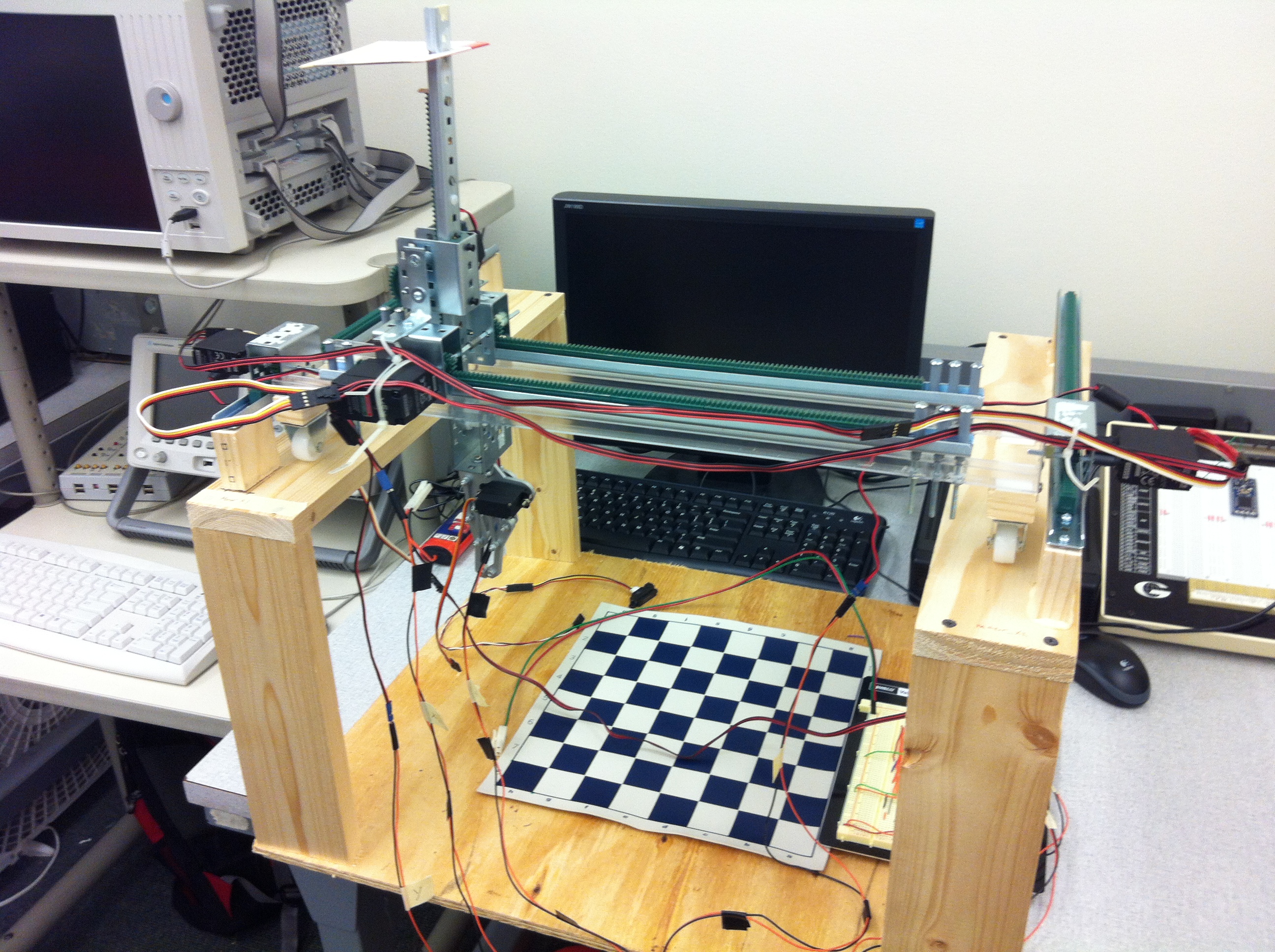
Movement
Here is my contribution: Paul (Daniel) and I built this “robot”, having no prior mechanical engineering experience. Go us.
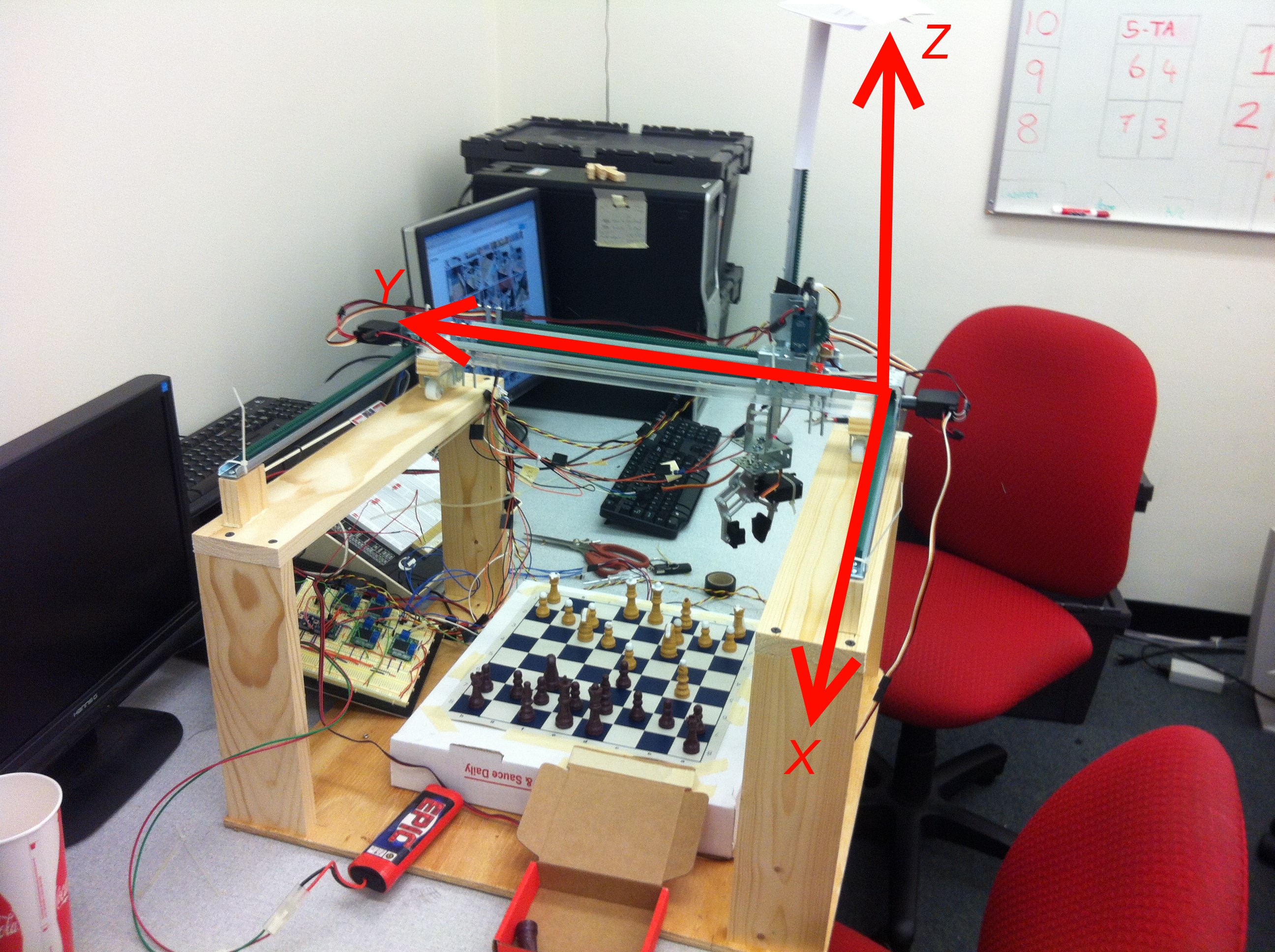
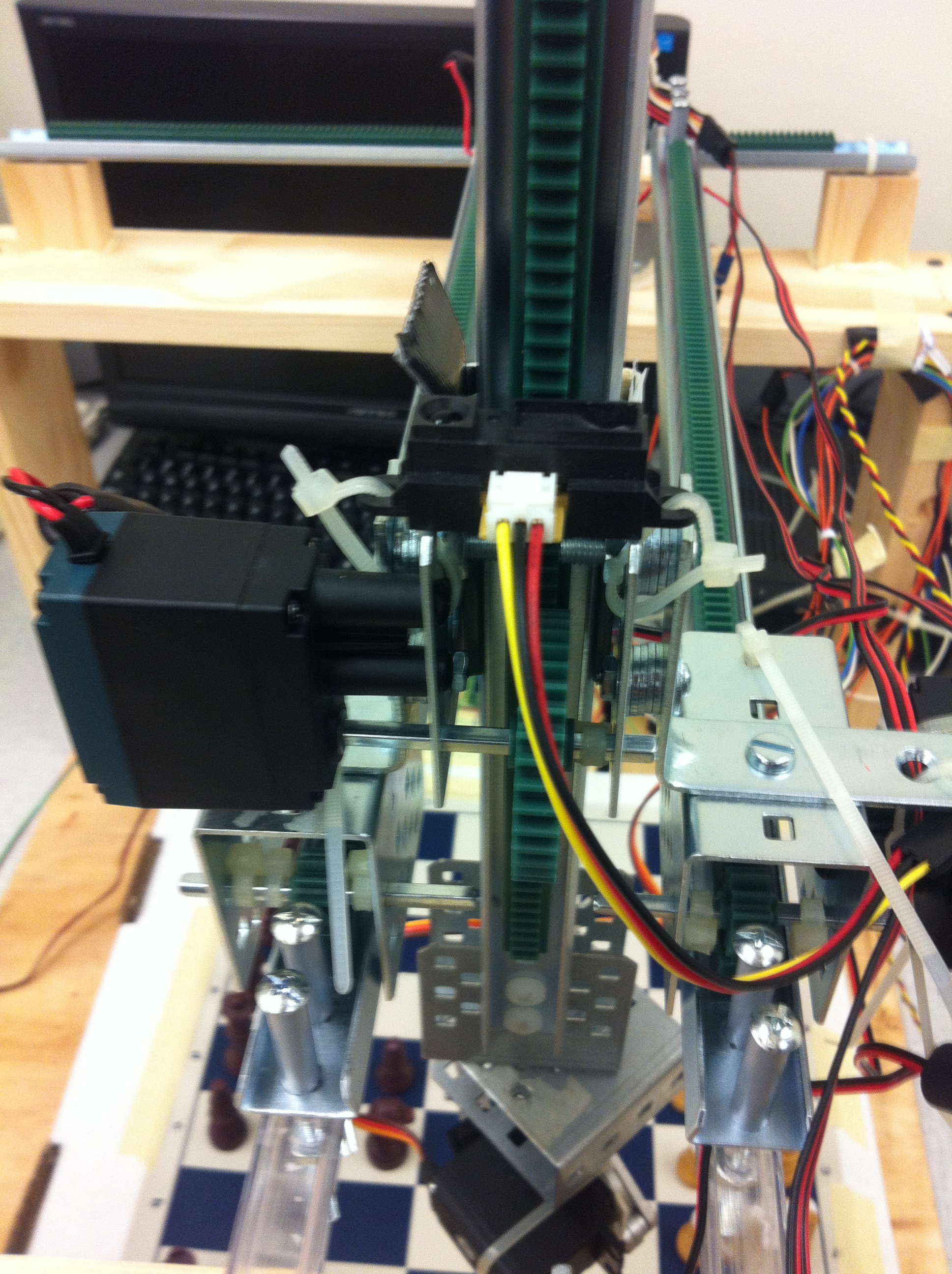
Look in the picture above for the standard axis orientations. For the sheer span, two motors are needed to realize movement in the x axis. Here are the motors and a close up picture of how they move:
When the X motors turn, the gear translates the rotational movement into linear movement (the technical term for the setup is a pinion (the gear) and rack (toothed rails)). When they move, they carry the platform in between them along the x axis. Resting on the Y axis is a similar setup to the X axis, just in a smaller scale. Because of this, it only requires one motor.
Here’s a closeup of the platform in between X motors, on which this travels:
Wire management leaves something to be desired
Lastly, sandwiched between the double rails is the section for the Z motor to rest on:
In this picture, the double rails are the Y axis, and the motor on the left controls the z axis. Unlike the X and Y axis, which moves with respect to a fixed rack, the Z axis motor is fixed, and moves the arm up and down.
This picture deserves some explanation. Our rig uses simple DC motors from Vex to turn the gears. Vex also produces these encoders as separate I2C devices that attach to the back of the motors. The encoders are quadrature encoders that will allow us to poll them to determine the current position. All motors are identical (with the exception of the Y axis motor, which is just slightly more powerful), so they can all be affixed with the same encoder. It was an oversight on my part to not buy enough. With more time, we would have waited until we bought another, but we received all the parts with about a week and half to finish the project. Instead, we opted for using a distance sensor, shown above. The distance sensor is fixed on the Z axis bracket, and senses the distance between it and this variable barrier:
MacGyver would be proud. (That’s Paul in the picture)
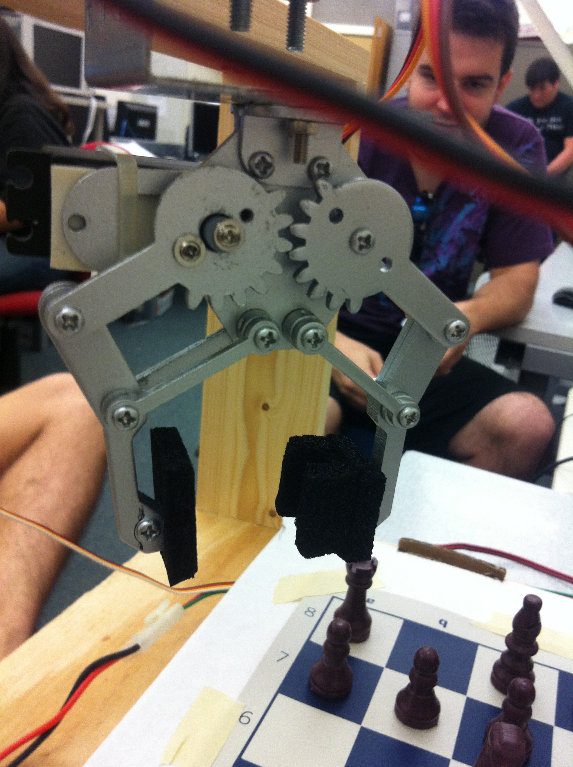
On the other end of the Z axis arm is the claw:
We glued some foam pieces onto the end, so as to allow us to grab pieces more easily. The claw is controlled by a servo motor, with only two set positions in code: OPEN and CLOSE. When X, Y, and Z are done moving, the claw is then free to grip or release a piece.
As mentioned, the encoders on the motor is important, since it provides feedback. PID loops control all the motors (well, actually just PI in the case). I couldn’t quite tune it to get what I wanted to happen, so a fix is that the motors just get “close enough”, and then moves with the minimum speed to its destination. You may see this in some of the videos: the rig moves with variable speed towards its destination, stops, and crawls for some small amount. This has successfully fixed overshoots without too much delay.
When the current move is done, the engine updates the game, and CarlsenBot waits for the next move.
Hope you’ve enjoyed reading. Please email me at ben.p.yeh@gmail.com if you have any questions.
Here are some more videos:
https://www.youtube.com/watch?v=M3mgB6fCdAE (This video shows what happens in a checkmate. It’s not as dramatic as I’d like it to be. If you pause at the end where show the terminal results, a line that says “…mate!” is printed at the top.
We finally got this moving towards the end of the day yesterday. It needs some fine-tuning, and integration with the other part of the project: the voice control, which my other teammates have been working on in parallel. Be looking for that in another post soon!
Since last time, my rig got an upgrade in placement of the y-axis movement racks and z-axis movement racks. It looks pretty sweet, I know. It’s still got some ugly wires, but believe me, it was looking much worse earlier. May have to get some tubing for the remaining wires.
Here’s the rig controller. 4 identical H-bridges control each of the motors. I will probably adjust it so all the wires stay flush against the breadboard.
Lastly, here’s the Sparkfun claw affixed to the end of the z-axis. It is the only thing that’s not part of the system, as evident by its leads unconnected. I’m heading back to the lab to fix that as soon as I finish eating. You will also see in the back the distance sensor we plan to use to determine the height of the z-axis. You might wonder why don’t we just use the encoder? Because I had an oversight, and didn’t get enough encoder attachments for the motors.
A simple test revealed that everything moved without fail, which is a huge relief. It means that this rig is ready for a day of programming. Look out for the next update!
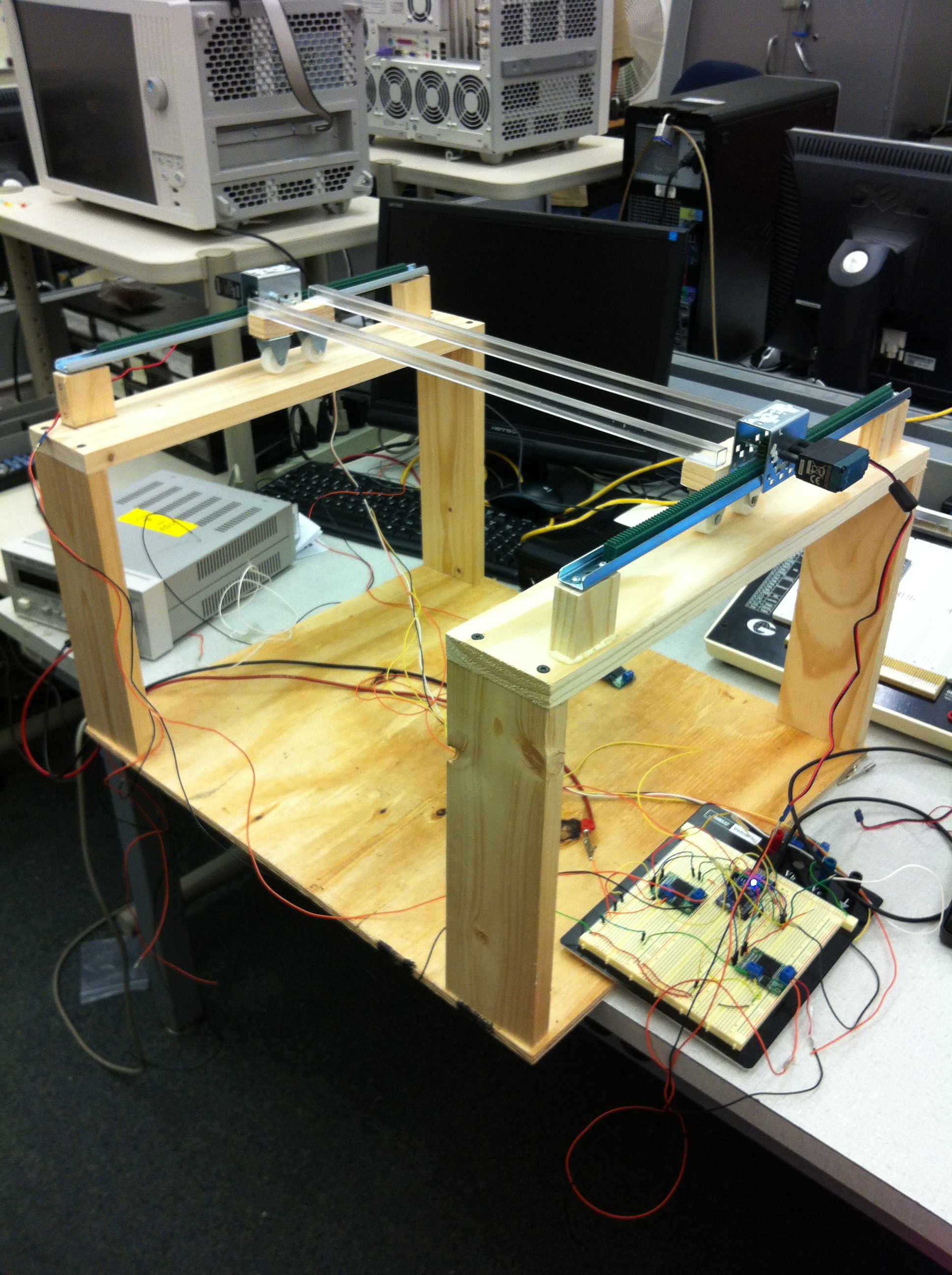
Since the last time, the rig’s got one new edition: racks to enable movement in one direction. It looks like this:
And video of “movement”:
I should have known better than to film vertically… The program runs a simple movement command for a short time, at the end of which I reset the microcontroller and step back to get the shot. Let it be known I do terrible prototype wiring. It will no doubt be cleaned up as we progress.
That being said, it’s awesome to finally see movement, after having so many setbacks. There was going to be another problem though: the motor movements are tracked with an encoder on one of the motors, just one though, so it’s possible the other one will lag. That’s been fixed by changing the other motor to one with an encoder, so this picture actually isn’t the one that’s most recent.
I thought programming was going to be a huge headache. And it was/is. I don’t know a whole lot about controls, and until I know a little bit more, movement is going to be a little naive: move towards desired position at full speed, and ramp down speed as platform approaches.
Here was another thing that was testing me as I was programming. The vex motor encoder is an i2c device, and the mbed microcontroller only has two i2c sda/scl pair of output pins. We are using a minimum of at least 3 encoders, so at least two encoders will be put on the same bus. To distinguish between the encoders on the same bus, you have to change their address (I’ll assume you know the basics of i2c from here). According to the datasheet for the encoder, you can change the address by opening up communication with the default address of 0x60, then writing the value 0x40, which is the address of “change default address” register, followed up by a final write of the desired register address (which should be in the range of 0x20-0x5E). The mbed i2c library is a little strange, because these two should do the same thing…but they don’t:
char changeAddr = 0x4D; // change address register
char newAddr = 0x20; // new address
i2c.write(0x40, &changeAddr, 1); // tell encoder I want to change default address
i2c.write(newAddr); // write new address

// that didn't work, but this did:

char changeAddr[2] = {0x4D, 0x20}; // put values to write in an array
i2c.write(0x40, changeAddr, 2);
the mbed’s i2c API specifies two versions of the write method, write(addr, char*, int) where the first argument is the address of the device, the second is a pointer to the values being written (hence why in the first try, and the third is the number of bytes to write. The other write is just write(byte) which writes a single value on the line. I thought after sending the device the value 0x4D, it knows that I am sending a value of the new address I want. But that can’t be done in a separate write. The “write” method includes the start and stop commands, so that was probably why. That took me way too long to figure out. Not enough experience working with i2c I suppose.
The encoders are also a bit different from other i2c devices in that multiple devices on a bus are actually daisy chained together, as opposed to devices attaching themselves to the bus like the other devices I’ve worked with, and there is a register that tells each device in the chain whether to pass through the clock and data along. If it does not, it is called a terminator. This is set in a register. If you do in fact want an i2c bus, you must disable the terminator register, and the next device can be initialized just as in the above.
Hopefully this phase of the programming will be done soon, and what I learn can be applied to movements in the other axis.
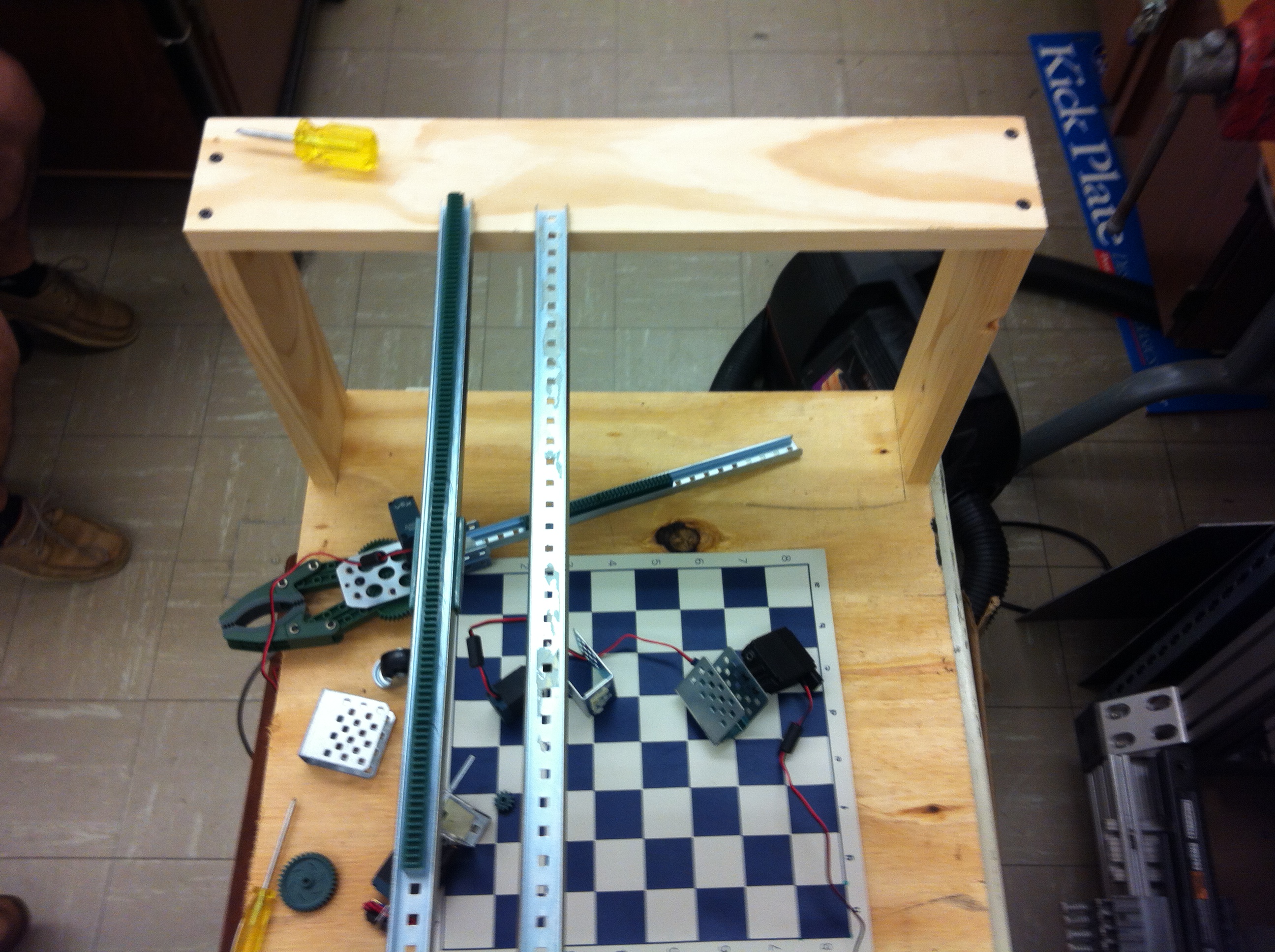
Some time ago I announced my final project for my Embedded Systems class: a voice activated chess-playing robot. Turns out another group did something similar a couple semesters ago, and they called it Kasparobot, clearly named after Gary Kasparov. It played with a chess engine by registering moves through OpenCV. Inspired by the name, I’ve christened our robot CarlsenBot, after Magnus Carlsen. I spent a few days looking at similar projects, namely this one: letsmakerobots.com/node/20833. It’s very well documented, and the various pictures help immensely. I’m very glad I found this, as it will provide a most excellent skeleton for my own project. My team and I spent a few hours digging through the parts in the lab and rigging together this setup:
Zoom in on the first picture. The green thing is a toothed rack, which turns rotary motion from a motor into linear motion with a gear that travels on the rack. We plan to place racks on the two arches to create movement along one axis, and create a movable platform positioned by motors and pinions, that will allow movement in the other two axis. You can see a claw that looks like it came from the same set we found these racks.
* To my annoyance the arches are slightly less than parallel, but I suppose if the racks are position parallel, it doesn’t really matter.
We will have to order a few new parts pronto, and assemble the platform I have in mind.
In parallel, we also have to get a program running to recognize dictated commands. For that, I think we might use this: http://msdn.microsoft.com/en-us/vstudio/cc482921.aspx. We’ve also got another option in EasyVR, which is a voice recognition hardware module: https://www.sparkfun.com/products/10685. It’s got an advantage of having a library already created by some other user on our microcontroller platform, but has the disadvantage of needing to be trained.
Hopefully a rough prototype can be completed this week, and finished next week, with plenty of time to debug before the demo.
For the final project in my embedded systems class, I’ve decided to build a voice controlled chess robot. I’ve got three other people working with me now so it should be manageable (or, it turns out to be a really easy project and we coast for the rest of the semester).
Just off the top of my head, here’s what we have to get done:
– find a voice recognition engine. For this we might use a EasyVR module, or Microsoft’s Speech SDK. I think EasyVR has to be trained, and I’d really like it to be independent of speaker, so that anybody can sit down and dictate.
– use the mbed to control motors that move a pick-and-place machine. Luckily mbed’s huge support will make this easy, hopefully. Encoder and motor libraries already exist, so I’ll be taking advantage of that.
– build the chassis for the pick-and-place machine.
 The idea is simple: to make a robotic limb mimic a human user’s arm. However, I won’t go into details in this post. The next posts will go into the project in more detail, as well as updates into the current progress. So excited!